Rotating electrical machine and hybrid drive unit provided with the same

a technology of rotating electrical machines and hybrid drive units, which is applied in the direction of propulsion by batteries/cells, electric devices, transportation and packaging, etc., can solve the problems of lowering the power transmission efficiency, and achieve the effect of reducing loss

Inactive Publication Date: 2007-04-26
TOYOTA CENT RES & DEV LAB INC
View PDF5 Cites 46 Cited by
  • Summary
  • Abstract
  • Description
  • Claims
  • Application Information

AI Technical Summary

Benefits of technology

[0009] Under the circumstances described above, the present invention provides a rotating electrical machine in which loss can be reduced and a hybrid drive unit provided with such an electrical machine.
[0011] According to the invention, the third rotor of the synchronous machine and the first rotor of the induction machine are independently rotatable, and a transmission path based on a mechanical path via the second rotor and a transmission path based on an electrical path via the second rotor conductor and the first rotor conductor are disposed as the power transmission path between the third rotor and the first rotor. The power transmission through the electrical path via the second rotor conductor and the first rotor conductor can be conducted without carrying out the electrical power conversion by an electrical power converter such as an inverter, so that the loss caused at the time of the power transmission through the electrical path can be reduced. Thus, the present invention can reduce the loss caused at the time of the power transmission between the third rotor and the first rotor.

Problems solved by technology

Therefore, the loss caused when the power is transmitted through the electric path increases, resulting in a problem that power transmission efficiency is lowered.

Method used


Image

  • Rotating electrical machine and hybrid drive unit provided with the same
  • Rotating electrical machine and hybrid drive unit provided with the same
  • Rotating electrical machine and hybrid drive unit provided with the same

Examples


Embodiment Construction

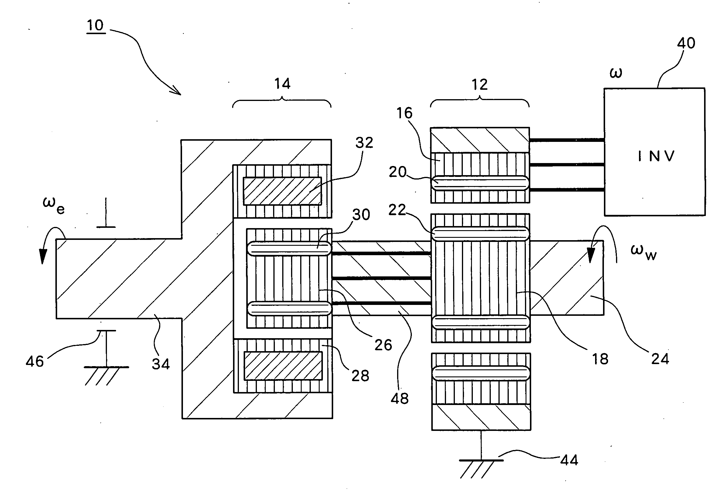
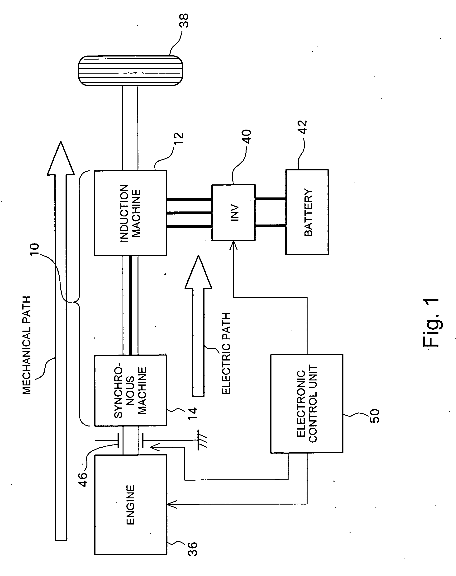
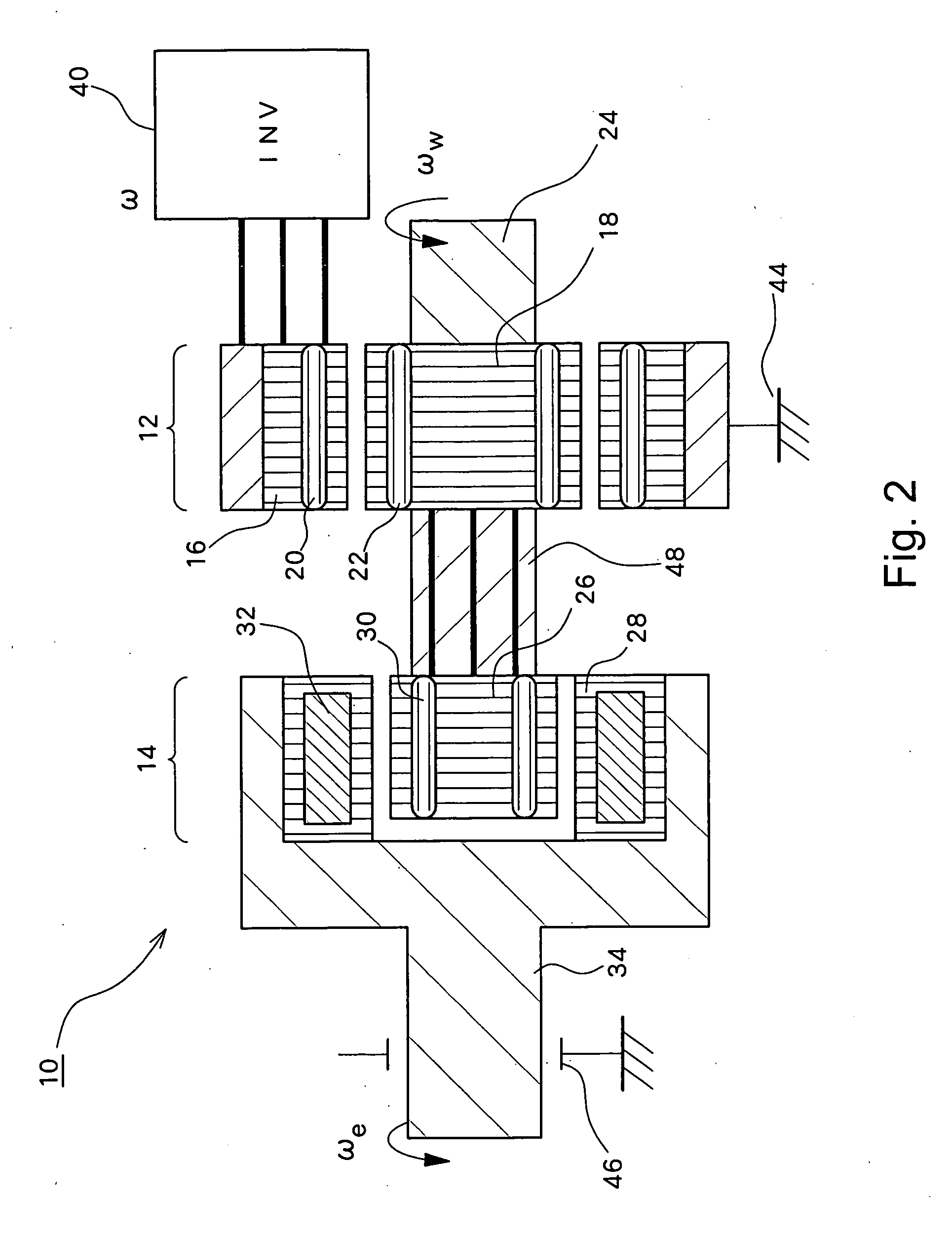
[0025] Preferred embodiments of the invention will be described below. FIG. 1 and FIG. 2 are diagrams schematically showing the structures of a hybrid drive unit having a rotating electrical machine according to an embodiment of the invention. FIG. 1 schematically shows the entire structure, and FIG. 2 schematically shows the structure of a rotating electrical machine 10. The hybrid drive unit according to this embodiment has an engine (internal combustion engine) 36 capable of producing power, and the rotating electrical machine 10 disposed between the engine 36 and a wheel 38. Also, the rotating electrical machine 10 has an induction machine 12 coupled to the wheel 38 and a synchronous machine 14 disposed between the engine 36 and the induction machine 12. For example, the hybrid drive unit according to this embodiment can be used as a power output device for driving a vehicle.

[0026] The induction machine 12 includes a stator (stator) 16 which is fixed to an outer frame 44 and a ...


PUM


Abstract

An induction machine includes a stator provided with stator windings and a first rotor provided with first rotor windings, and generates an induction current in one of the stator windings and the first rotor windings by a rotating magnetic field generated in the other of the stator windings and the first rotor windings. A synchronous machine includes a second rotor which is provided with second rotor windings connected to the first rotor windings and coupled to the first rotor, and a third rotor which is provided with permanent magnets and rotatable independent of the second rotor, and a torque acts between the second rotor and the third rotor due to the interaction between the rotating magnetic field generated in the second rotor windings and the field flux generated in the permanent magnets.

Description

BACKGROUND OF THE INVENTION [0001] a) Field of the Invention [0002] The present invention relates to a rotating electrical machine capable of performing power generation and electric power generation, and a hybrid drive unit provided with the same. [0003] b) Description of the Related Art [0004] For a hybrid drive unit having an engine and an electric motor as power generation sources, there is proposed, for example, the structure shown in FIG. 8. In the structural example shown in FIG. 8, the power of an engine 136 is divided in two by a power distribution mechanism 137 which is comprised of a planetary gear mechanism. One half of the distributed power of the engine 136 is transmitted to a wheel 138, and the other half of the distributed power of the engine 136 is converted into electrical power generated by an electrical generator 114. The electrical power generated by the electrical generator 114 undergoes electrical power conversion by the inverters 140, 141 (from AC to DC by an...

Claims


Application Information

Patent Timeline
Patent Type & Authority Applications(United States)
IPC IPC(8): H02K49/00H02K47/00H02P15/00B60K6/26B60K6/448H02K16/02
CPCB60K6/26B60L2240/423B60K6/448B60K6/48B60K2006/262B60L11/123B60L2220/12B60L2220/14B60L2220/52H02K7/006H02K16/00H02K16/02H02P2207/03Y02T10/6217Y02T10/6221Y02T10/6243Y02T10/641Y02T10/642Y02T10/7077Y02T10/6239B60L7/14B60L11/14B60L15/20B60L15/2009B60L2210/40B60K6/445B60L50/16B60L50/61Y02T10/62Y02T10/64Y02T10/70Y02T10/7072Y02T10/72
Inventor MORIYA, KAZUNARIINAGUMA, YUKIOFUMA, HIROO
Owner TOYOTA CENT RES & DEV LAB INC
Why Eureka
Try Eureka