Steam turbine

a technology of steam turbine and crossover duct, which is applied in the direction of machines/engines, stators, liquid fuel engines, etc., can solve the problems of increased exhaust steam loss, critical failure, and inability to neglect the loss in the cross-over duct, so as to reduce pressure loss and structure excellently

Inactive Publication Date: 2010-10-19
MITSUBISHI HITACHIPOWER SYST LTD
View PDF4 Cites 0 Cited by
  • Summary
  • Abstract
  • Description
  • Claims
  • Application Information

AI Technical Summary

Benefits of technology

[0005]The cross-over duct is just a mere passage. A loss (pressure loss) generated inside the cross-over duct could be neglected while it was relatively smaller than a loss in the entire system including turbine blades. However, since the performance of a turbine itself is significantly enhanced nowadays, a loss in the cross-over duct cannot be neglected in order to increase power generation efficiency of the entire power plant.
[0007]FIG. 3 of JP-A-11-229818 mentioned above illustrates a structure in which an exhaust steam outlet is one-on-one connected to an associated exhaust steam inlet. In cross-over ducts of this type, bent portions extend aslant to spread leftward and rightward relative to a rotor shaft instead of not extending vertically from the rotor shaft. This provides a shape that can alternately arrange two cross-over ducts having the same structure without intersecting them with the result that a loss can be reduced.
[0009]An object of the present invention is to provide a steam turbine having a cross-over duct that can reduce a pressure loss occurring therein and is structured excellently in view of strength.
[0011]According to the present invention, it is possible to provide a steam turbine having a cross-over duct that can reduce a pressure loss occurring therein and is structured excellently in view of strength.

Problems solved by technology

However, since the performance of a turbine itself is significantly enhanced nowadays, a loss in the cross-over duct cannot be neglected in order to increase power generation efficiency of the entire power plant.
Therefore, flow rate balance in the turbine deviates from a design point, and it may increase an exhaust steam loss.
Since the turbine blades are rotated at very high-speed, even slight deviation of the central axis of the rotor is likely to cause a critical failure.
In particular, a bulk plant produces a problem with cost and reliability.

Method used


Image

  • Steam turbine
  • Steam turbine
  • Steam turbine

Examples


Embodiment Construction

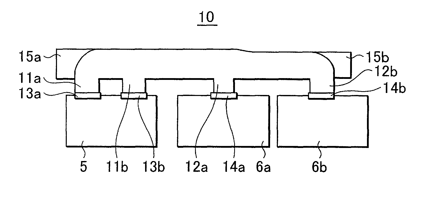
[0021]In a steam turbine, a cross-over duct is adapted to allow steam discharged from an intermediate pressure turbine (or a high pressure turbine) to flow in a low pressure turbine. The basic structure of the cross-over duct includes some different types depending on the number of casings for the intermediate pressure turbine and low pressure turbine. An embodiment of the present invention describes a steam turbine in which two exhaust steam outlets are provided on an intermediate pressure turbine side, and similarly two exhaust steam inlets are provided on a low pressure turbine side, and the exhaust steam outlets and the exhaust steam inlets are located on the same straight line.

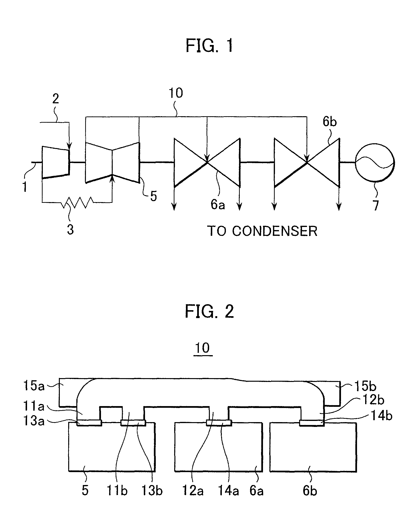
[0022]FIG. 1 schematically shows a systematic diagram of the most general steam turbine in such a case. The shape and role of the most typical cross-over duct will be described below with reference to FIG. 1.

[0023]FIG. 1 illustrates a steam turbine of a tandem (spit-style) compound four-flow type. This st...


PUM


Abstract

In a steam turbine having a cross-over duct for delivering steam discharged from an intermediate pressure turbine to low pressure turbines, the intermediate pressure turbine provides two outlets for discharging exhaust steam, the low pressure turbine provides two inlets, and the outlets and the inlets are arranged on the same straight line as viewed from a planar direction. One of the outlets and one of the inlets which are close to each other are connected through a cross-over duct, the other of the outlets and the other of the inlets which are far from each other are connected through another cross-over duct, and the cross-over ducts are arranged to be at two stages in the up-down direction.

Description

BACKGROUND OF THE INVENTION[0001]1. Field of the Invention[0002]The present invention relates to a structure of a cross-over duct for a steam turbine.[0003]2. Description of the Related Art[0004]In a steam turbine, a connection pipe adapted to allow the steam discharged from an intermediate pressure turbine (or high pressure turbine) to flow into a low pressure turbine is generally referred to as a cross-over duct. Incidentally, examples of conventional techniques pertaining to the cross-over duct include the technique disclosed in JP-A-11-229818 (FIG. 1).SUMMARY OF THE INVENTION[0005]The cross-over duct is just a mere passage. A loss (pressure loss) generated inside the cross-over duct could be neglected while it was relatively smaller than a loss in the entire system including turbine blades. However, since the performance of a turbine itself is significantly enhanced nowadays, a loss in the cross-over duct cannot be neglected in order to increase power generation efficiency of th...

Claims


Application Information

Patent Timeline
Patent Type & Authority Patents(United States)
IPC IPC(8): F01D1/02
CPCF01D9/00F01D9/06
Inventor MIZUMI, SHUNSUKEIWANO, RYUICHIROISHIBASHI, KOJILEE, GOINGWON
Owner MITSUBISHI HITACHIPOWER SYST LTD
Why Eureka
Try Eureka