Ceramic laminated device and method for manufacturing same

a laminated device and ceramic technology, applied in the direction of fixed capacitors, variable capacitors, fixed capacitor details, etc., can solve the problems of affecting the reactivity and reducing the q value as a device, so as to achieve high q value, suppress the effect of ag during firing and high q valu

Inactive Publication Date: 2010-11-02
PANASONIC CORP
View PDF11 Cites 0 Cited by
  • Summary
  • Abstract
  • Description
  • Claims
  • Application Information

AI Technical Summary

Benefits of technology

[0008]The present invention is directed to address these problems and provide a ceramic laminated device having a high Q value and a low loss at high yield. The ceramic laminated device is provided by minimizing the reaction between a dielectric ceramic and an Ag electrode thereof and inhibiting and controlling segregation of a secondary phase, such as Si or Zn, i.e. a component of glass or additive, and a multiple oxide thereof, in the proximity of the electrode.
[0012]According to the ceramic laminated device and the method for manufacturing the ceramic laminated device of the present invention, even when a ceramic laminated device is formed to have an Ag internal electrode in a dielectric ceramic that can be sintered at a low temperature of approximately 900° C. and has a high dielectric constant and a high Q value, reactivity to Ag during firing can be suppressed low. Thus, a high Q value as a device can be maintained and a loss can be reduced. As a result, a small ceramic laminated device having excellent characteristics with few characteristics variations can be provided stably.

Problems solved by technology

However, the conventional art has the following problem, although the material can be sintered at approximately 900° C., at which Ag can be fired at the same time.
This reaction makes the width or thickness of the electrode smaller than the designed value and thus hinders imparting sufficient characteristics.
Further, segregation of Si or Zn, i.e. a component of the glasses or additives, or a multiple oxide thereof in the proximity of the electrode as a secondary phase is likely to decrease the Q value as a device and increase a loss.

Method used


Image

  • Ceramic laminated device and method for manufacturing same
  • Ceramic laminated device and method for manufacturing same
  • Ceramic laminated device and method for manufacturing same

Examples


Embodiment Construction

Exemplary Embodiment

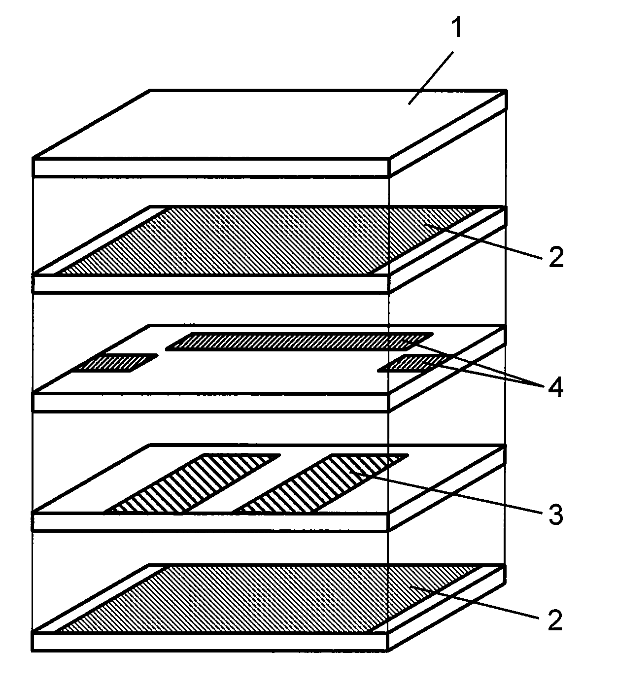
[0022]Hereinafter, a description is provided of a ceramic laminated device and a method for manufacturing the ceramic laminated device in accordance with the exemplary embodiment of the present invention.

[0023]As a first ingredient of the starting material, BaCO3, Nd2O3, TiO2, and Bi2O3 having a chemically high purity (of 99 wt % or higher) are used. When the composition of the respective components is expressed as xBaO-yNd2O3-zTiO2-wBi2O3 (where x+y+z+w=100, and each of x, y, z, and w is a molar ratio), preferably, the composition range is as follows: 12≦x≦16, 12≦y≦16, 65≦z≦69, and 2≦w≦5. In this exemplary embodiment, Nd2O3 is used as a rare-metal oxide. However, a rare-metal oxide other than Nd oxides, such as La2O3 and Sm2O2, may be used. Alternatively, a part of Nd can be substituted with another rare-metal element. The above powder and pure water are mix in a ball mill for 18 hours. After mixing, the obtained slurry is dried, placed in an alumina crucible, a...


PUM

PropertyMeasurementUnit
thicknessaaaaaaaaaa
thicknessaaaaaaaaaa
melting pointaaaaaaaaaa

Abstract

The present invention relates to a ceramic laminated device including a dielectric ceramic and an Ag electrode. In a dielectric ceramic that can be sintered at low temperatures and has a high dielectric constant and Q value, reactivity between the ceramic and Ag during sintering is suppressed low and segregation of specific elements in the proximity of the electrode is controlled. Thus, a filter having a high Q value and low loss is produced stably. For this purpose, in a ceramic laminated body including at least a ceramic and a Si-containing glass, a ratio of A / B, i.e. a ratio of a Si element concentration (A) within a range at a distance of 5 μm or smaller from the Ag electrode to a Si element concentration (B) within a range at a distance larger than 5 μm from the Ag electrode, is set equal to or smaller than 2.

Description

RELATED APPLICATIONS[0001]This application is the U.S. National Phase under 35 U.S.C. §371 of International Application No. PCT / JP2007 / 054281, filed on Mar. 6, 2007, which in turn claims the benefit of Japanese Application No. 2006-070599, filed on Mar. 15, 2006, the disclosures of which Applications are incorporated by reference herein.TECHNICAL FIELD[0002]The present invention relates to a ceramic laminated device and a method for manufacturing the ceramic laminated device.BACKGROUND ART[0003]With recent development of communication technology utilizing electromagnetic waves in the microwave range for use in a portable telephone and a wireless local area network (LAN), demand for downsizing the equipment is further increasing. In order to downsize such terminal equipment, downsizing high-frequency devices constituting the equipment, such as a high-frequency filter and a resonator, is necessary.[0004]Examples of such high-frequency devices include a laminated dielectric filter. The...

Claims


Application Information

Patent Timeline
Patent Type & Authority Patents(United States)
IPC IPC(8): H01G4/06H01G4/005
CPCH01G4/0085H01G4/129H01G4/30H03H7/0115H05K1/0306Y10T29/435H05K3/4611H05K3/4629H03H2001/0085
Inventor SAITO, RYUICHISHIGENO, KOICHIKAGATA, HIROSHI
Owner PANASONIC CORP
Why Eureka
Try Eureka