
Narrow band excimer laser and wavelength detecting apparatus

a wavelength detection and narrow band technology, applied in the direction of optical radiation measurement, instruments, active medium materials, etc., can solve the problems of high degree of coherence of output light beam, spectrum purity degradation, and difficulty in achieving 100% locking efficiency, so as to reduce loss, increase the number of prisms, the effect of large transmissivity

Inactive Publication Date: 2003-12-30
KOMATSU LTD
View PDF32 Cites 0 Cited by
  • Summary
  • Abstract
  • Description
  • Claims
  • Application Information

AI Technical Summary

Benefits of technology

By selectively oscillating a linearly polarized wave which is substantially parallel with the beam expanding direction of the prism beam expander, the loss can be reduced even though the incident angle to the prism is large or the number of the prisms is increased. This is because a linearly polarized wave parallel with the beam expanding direction of the prism beam expander has a large transmissivity even the incident angle to the prism is large. With this construction, the narrow band laser device can generate a large output with a small spectrum line width.

Problems solved by technology

With this method, however, although a relatively large output power can be obtained, there are such defects that misshots occur, that it is difficult to obtain 100% locking efficiency, and the spectrum purity degrades.
Furthermore, in this method, the output light beam has a high degree of coherency so that when the output light beam is used as a light source of the reduction type projection aligner, a speckle pattern generates.
Conversely, when the number of the space transverse modes increases, the speckle pattern becomes difficult to generate art.
Since generation of speckle pattern causes a serious problem, this technique can not be adopted in the reduction projection aligner.
This system, however, cannot obtain a very narrow spectral bandwidth.
In addition there are problems in that the power loss is large due to the insertion of the air gap etalon.
Further, it is impossible to greatly increase the number of the space transverse modes.
Furthermore, the air gap etalon has a problem of poor durability.
In the construction in which a pin hole is disposed in a resonator, however, the output becomes greatly reduced and the number of space transverse modes necessary for preventing generation of a speckle pattern decreases, so that such construction can not be used.
However, when the magnifying power of the prism beam expander becomes large, the incident angle of the laser beam to a prism of the prism expander becomes large or it becomes necessary to increase the number of prisms, thereby increasing the loss.
As a result, a large output cannot be produced.
However, it is difficult to precisely control the pressure in the air gap and the ambient temperature.
Therefore, it is impossible to detect the absolute wavelength at a high accuracy.
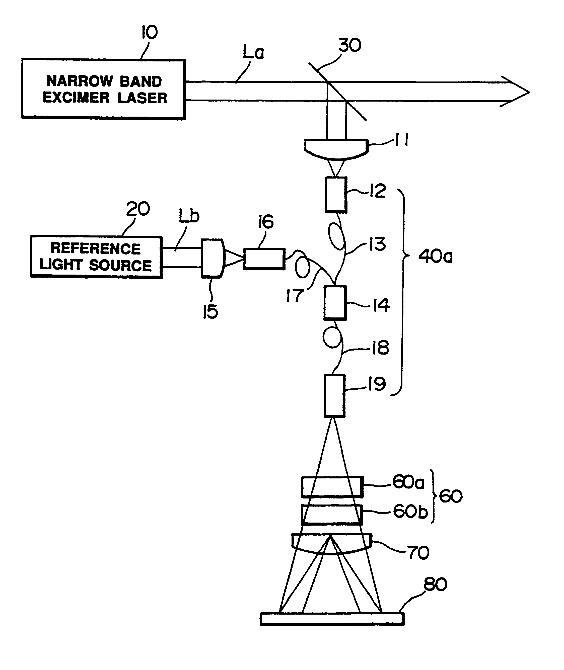
However, in this apparatus, since the output of the monitor etalon is directly inputted to the beam detector, the beam to be detected and the reference beam cannot be inputted to the beam detector with a sufficient beam quantity, and an interference fringe cannot be formed on the beam detector.

Method used


Image

  • Narrow band excimer laser and wavelength detecting apparatus
  • Narrow band excimer laser and wavelength detecting apparatus
  • Narrow band excimer laser and wavelength detecting apparatus

Examples


Embodiment Construction

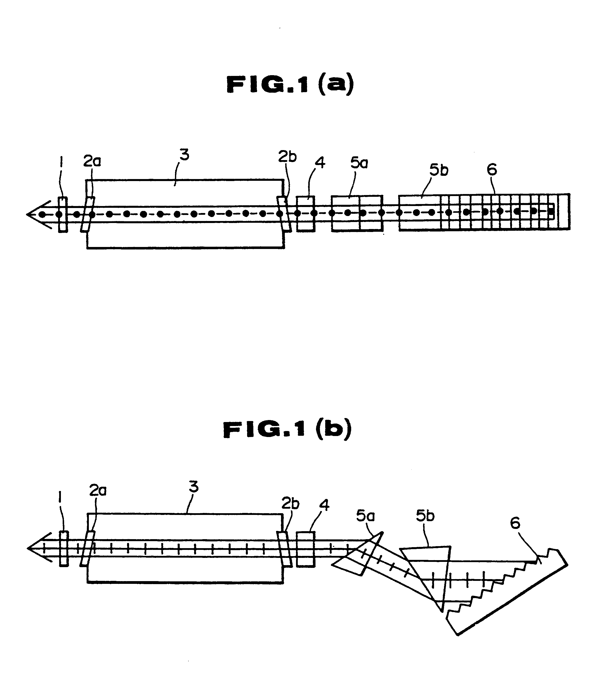
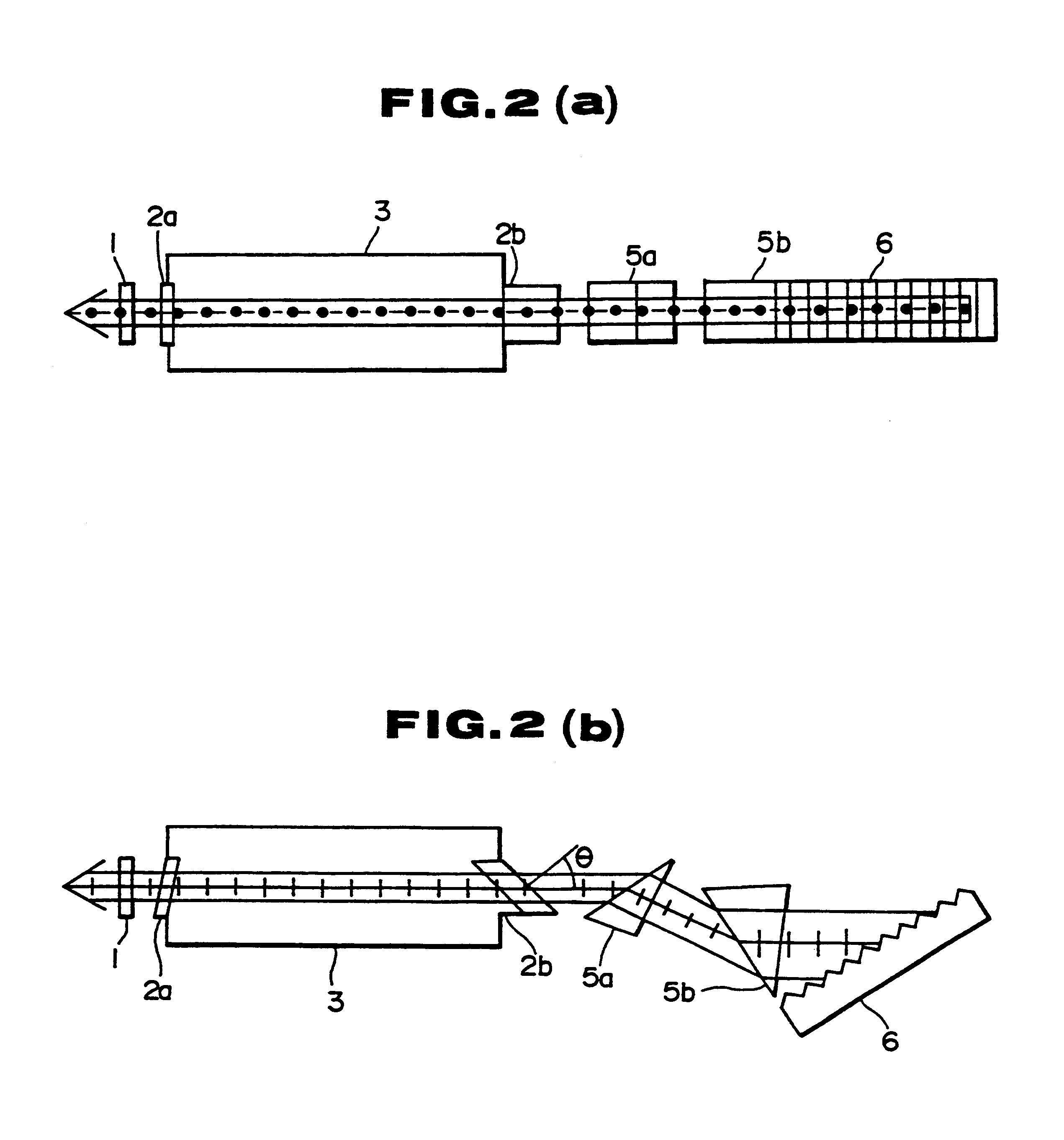
The embodiments-of this invention will now be described with reference to the accompanying drawings. The narrow band excimer laser shown in FIGS. 1(a) and 1(b) comprises a front mirror 1, and a grating 6 acting as a rear mirror and a wavelength selective element. Between the front mirror 1 and the grating 6, a laser chamber 3, a polarizing element 4, and two prisms 5a and 5b acting as a beam expander (prism beam expander) are provided. Thus, a laser chamber or cavity is constructed between the front mirror 1 and the grating 6.

The laser chamber 3 is filled with a laser gap containing KrF, etc. which can circulate in the chamber 3. For the purpose of exciting the laser gas, discharge electrodes (not shown) are provided in the laser chamber 3. Windows 2a and 2b are provided at both ends of the laser chamber 3 at predetermined angles.

The purpose of the grating 6 is to select a beam having a specific wavelength by utilizing diffraction of light beam. The grating 6 is provided with a numb...


PUM


Abstract

A narrow band excimer laser and a wavelength detecting apparatus are suitable for use as a light source of a reduction projection aligner of a semiconductor device manufacturing apparatus. In the excimer laser, the ruling direction and the beam expanding direction of a prism beam expander are made substantially coincide with each other, and a polarizing element causing selective oscillation of a linearly polarized light wave substantially parallel with the beam spreading direction of a prism beam expander is contained in a laser cavity. A window at the front or rear side of a laser chamber is disposed such that the window make a Brewster's angle with respect to the axis of the laser beam in a plane containing the beam expanding direction of the prism expander and the laser beam axis. An anti-reflection film which selectively prevents reflection of a polarized light component substantially parallel to the direction of beam expanding of a prism beam expander is coated on one surface of a prism that constitutes the prism beam expander. The wavelength detecting apparatus is constructed to input a reference light and a light to be detected upon the etalon. The light transmitting through the etalon is condensed to focus on a light detector for detecting the wavelength of the laser beam based on interference fringe detected by the light detector.

Description

TECHNOLOGICAL FIELDThis invention relates to a narrow band excimer laser and a wavelength detection device, and more particularly to a narrow band excimer laser suitable for a light source of a reduction projection aligner for use in manufacturing semiconductors.BACKGROUND ARTAttention has been paid to the use of an excimer laser as a light source of reduction projection aligner (hereinafter called a stepper) for manufacturing semiconductor devices. This is because the excimer laser may possibly extend the light exposure limit to be less than (0.5 .mu.m since the wavelength of the excimer laser is short (for example the wavelength of KrF laser is about 248.4 nm), because with the same resolution, the focal depth is greater than a g line or an i line of a mercury lamp conventionally used, because the numerical aperture (NA) of a lens can be made small so that the exposure region can be enlarged and large power can be obtained, and because many other advantages can be expected.An exci...

Claims


Application Information

Patent Timeline
IPC IPC(8): G01J9/00G03F7/20G01J9/02H01S3/13H01S3/14H01S3/225H01S3/08H01S3/139H01S3/00
CPCG01J9/0246G03F7/70566G03F7/70575G03F7/70583H01S3/0014H01S3/08004H01S3/08009H01S3/1394H01S3/225
Inventor WAKABAYASHI, OSAMUKOWAKA, MASAHIKOKOBAYASHI, YUKIO
Owner KOMATSU LTD
Learn More