Hybrid-excited rotating machine, and vehicle with the hybrid-excited rotating machine

Active Publication Date: 2007-04-26
MITSUBISHI ELECTRIC CORP
View PDF9 Cites 126 Cited by
  • Summary
  • Abstract
  • Description
  • Claims
  • Application Information

AI Technical Summary

Benefits of technology

[0009] For an instantaneous start of the engine, it has been desired to improve the starting torque better. In order to have a higher torque in the device of the prior art, the permanent magnets have to be enlarged to increase total magnetic flux. As a result, the starting torque is improved, but the induced voltage at a no-load time rises. Even if the main magnetic flux is minimized, the voltage exceeds the supply voltage

Problems solved by technology

Even if the main magnetic flux is minimized, the voltage exceeds the supply voltage of the vehicle so that the power generation cannot be controlled.
However, it is difficult to weaken the main magnetic flux to a low voltage corresponding to that o

Method used


Image

  • Hybrid-excited rotating machine, and vehicle with the hybrid-excited rotating machine
  • Hybrid-excited rotating machine, and vehicle with the hybrid-excited rotating machine
  • Hybrid-excited rotating machine, and vehicle with the hybrid-excited rotating machine

Examples


embodiment 1

Mode of Embodiment 1

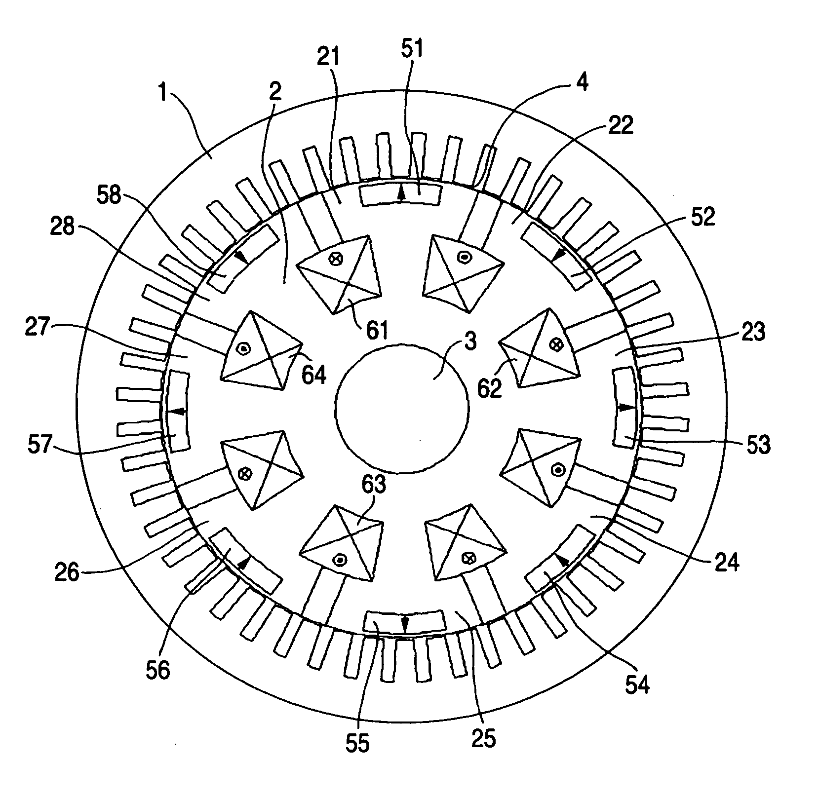
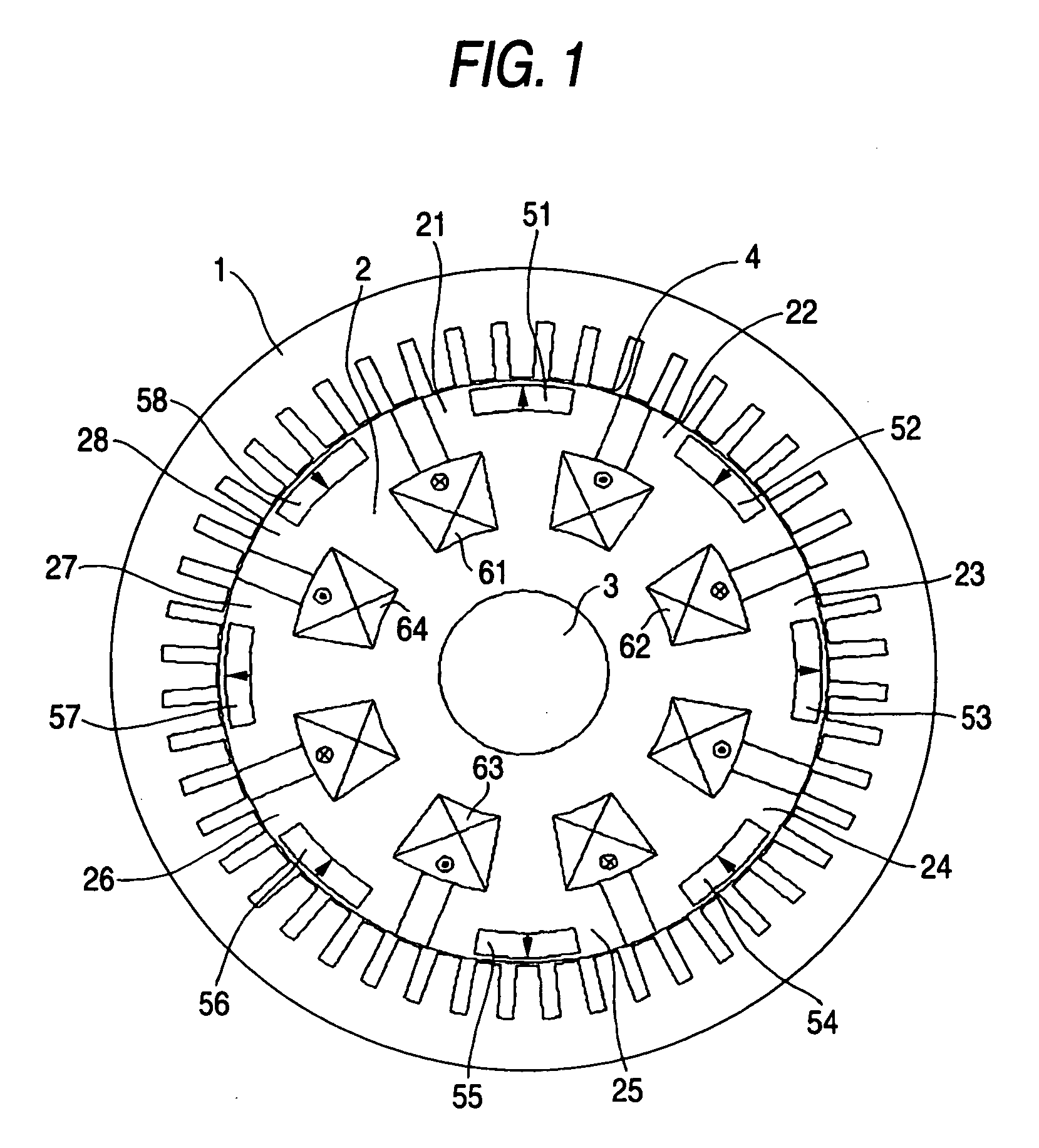
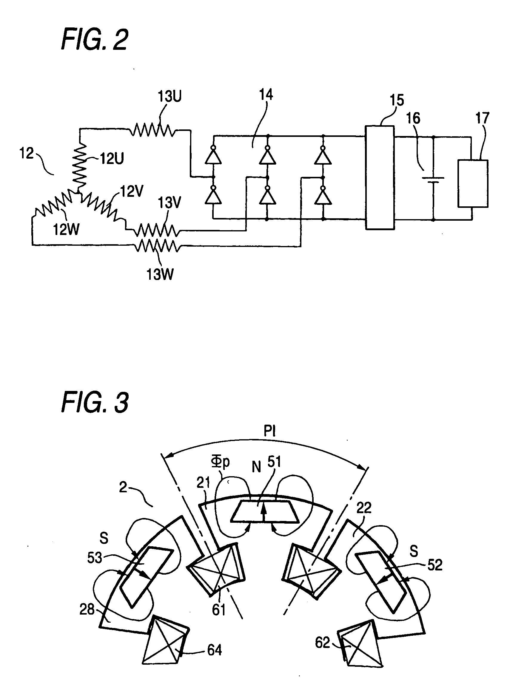
[0047]FIG. 1 is a transverse section of a hybrid-excited rotating machine for a vehicle according to Mode of Embodiment 1 of the invention, and FIG. 2 is an explanatory diagram showing the circuit of a stator winding. In FIG. 1, a stator 1 is equipped with stator iron core 11, in which annular magnetic sheets of an identical shape are laminated in the axial direction. Forty eight slots 111 are formed in the inner circumference of that stator iron core 11. In the forty eight slots 111 of the stator iron core 11, although not shown in FIG. 1, a stator winding 12 having a three-phase Y-connection is mounted as a distributed winding of an every-pole / every-phase 2. Here, the stator winding 12 may be a concentrated winding.

[0048]FIG. 2 shows a constitution relating to the stator winding 12, which is equipped with a U-phase winding 12U, a V-phase winding 12V and a W-phase winding 12W of the three-phase Y-connection, as described above. The U-phase winding 12U, the V-ph...

embodiment 2

Mode of Embodiment 2

[0072]FIG. 15 is an explanatory view showing a constitution of Mode of Embodiment 2 of the invention. In this Mode of Embodiment 2, as shown in FIG. 15, inter-pole permanent magnets 71 to 72 magnetized in the circumferential direction of the rotor are arranged between the individual rotor magnetic poles 21 to 28, i.e., between the inter-pole spaces. The inter-pole permanent magnets 71 to 78 have their magnetized directions alternately inverted.

[0073] According to this Mode of Embodiment 2, as shown in FIG. 15, the magnetic flux Φp1 according to the inter-pole permanent magnets 71 to 78 are added to intensify the magnetic flux so that the air gap magnetic flux density can be further enhanced. This magnetic flux is reversed in direction from the main magnetic flux Φp according to the permanent magnets 51 to 58 of the rotor magnetic poles 21 to 28, so that the center portion A of the rotor, as hatched in FIG. 15, can be relaxed in the magnetic saturation.

[0074] As...

embodiment 3

Mode of Embodiment 3

[0075] Mode of Embodiment 3 of the invention is a vehicle, in which the hybrid-excited rotating machine of Mode of Embodiment 1 or 2 is used as a generator driven for the power generation by the engine and as an electric motor for starting the engine.

[0076] Usually, the hybrid-excited rotating machine, as mounted on the vehicle, is used as the generator, when its rotor is driven by the vehicular engine, and as the electric motor when energized at its stator winding by the three-phase AC current. This rotating machine is used in the vehicle which has an engine mounted for an idling stop to improve the mileage. This vehicle is required to have a high starting torque in a low speed range for starting the engine quickly. At the same time, the output shaft has to be raised to the maximum rpm of 2,000 rev. / min. and to ten times or more of the basic revolving speed. This makes it necessary to control the field of the motor weakly over a wide range.

[0077] In case the b...


PUM


Abstract

A hybrid-excited rotating machine comprising: a stator winding 12 of a multi-phase Y-connection; a plurality of rotor magnetic poles 21, 22, 23, 24, 25, 26, 27, 28 fixed on a rotor shaft 3 at a predetermined spacing in the circumferential direction and confronting the inner circumference of said stator 1 through a air gap; a plurality of permanent magnets 51, 52, 53, 54, 55, 56, 57, 58 fixed at substantially central portions of said circumferential direction of said individual rotor magnetic poles and magnetized in the radial direction of said rotor shaft; and a plurality of field windings 61, 62, 63, 64, 65, 66, 67, 68 wound individually on said rotor magnetic poles.

Description

BACKGROUND OF THE INVENTION [0001] 1 . Field of the Invention [0002] The present invention relates to a rotating machine for a vehicle or the like, which is equipped at its rotor with permanent magnets and field windings so that it is excited in a hybrid manner by the permanent magnets and the field windings, and to a vehicle which is equipped with the hybrid-excited rotating machine. [0003] 2. Background Art [0004] The rotating machine having permanent magnets at its rotor is advantageous in that it is small but can generate a high torque, and is adopted in recent years for various applications. However, it fixes the quantity of magnetic flux that the rotor has the magnets. In case this rotating machine is employed as a generator, therefore, its output voltage is proportional to the revolving speed so that it widely changes in the application where the revolving speed range is wide as in a vehicular generator. Thus, it is difficult to apply the rotating machine to a vehicular gener...

Claims


Application Information

Patent Timeline
IPC IPC(8): H02K21/00H02K21/12
CPCH02K21/042
Inventor ARITA, HIDEAKIINOUE, MASAYAASAO, YOSHIHITOYAMAMOTO, TSUNENOBU
Owner MITSUBISHI ELECTRIC CORP
Why Eureka
Try Eureka