Magnetic field pulse current sensing for timing-sensitive circuits

a timing-sensitive circuit and pulse current technology, applied in the direction of magnetic measurements, pulse characteristics measurements, instruments, etc., can solve the problems of affecting the performance of the tof lidar system, its reflection being detectable, peak amplitude, etc., and achieve the effect of reducing the total flux and increasing the total magnetic flux

Active Publication Date: 2020-05-07
EFFICIENT POWER CONVERSION CORP
View PDF4 Cites 1 Cited by
  • Summary
  • Abstract
  • Description
  • Claims
  • Application Information

AI Technical Summary

Benefits of technology

[0015]In further embodiments, the pickup coil is a single loop configured to be arranged near the current conductor, which may be monolithically integrated onto a single semiconductor chip. In a further embodiment, the pickup coil may have one or more turns arranged to increase the total magnetic flux resulting from the current to be measured through the entirety of the coil while reducing the total flux from other sources. In other embodiments, a portion of the pickup coil is integrated on a semiconductor chip with the at least one threshold crossing detector, and a portion of the pickup coil is formed by die terminals and an external conductor. The external conductor may form part of a mounting substrate such as a printed circuit board including the current conductor.
[0016]The above and other preferred features described herein, including various novel details of implementation and combination of elements, will now be more particularly described with reference to the accompanying drawings and pointed out in the claims. It should be understood that the particular methods and apparatuses are shown by way of illustration only and not as limitations of the claims. As will be understood by those skilled in the art, the principles and features of the teachings herein may be employed in various and numerous embodiments without departing from the scope of the claims.

Problems solved by technology

The performance of ToF lidar systems is also affected by the amplitude of the laser pulse, with increasing pulse amplitude resulting in its reflection being detectable after traveling increasing distances.
However, the maximum amplitude of the laser pulse must comply with eye safety regulations, and the laser driver must limit the peak amplitude of the current pulse accordingly.
However, the output current pulses may be on the order of tens to hundreds of amperes (A) in some applications, which makes current sensing more complicated.
If extremely short pulses are required, such as the aforementioned ns pulses, the parasitic effects of current sensing circuits can be detrimental to the operation of the driver.
Even with mΩ values of RSHUNT, very large amplitude current pulses cause the shunt resistor 120 to dissipate large amounts of power as heat, which may damage other components on the circuit or unnecessarily strain the power supply or battery of the system.
Further, shunt resistor 120 may experience thermal drift as it heats up, changing its resistance and VSENSE such that computationally expensive compensation is necessary to precisely determine the start and end times and the peak amplitude of the current pulse.
The shunt resistor 120 directly measures IPULSE, which means it is placed within the main driver signal chain and disadvantageously increases the inductance of the main driver circuit.
The magnetic core can saturate at high currents and increases the inductance of the system such that operation of other components is affected.
Some magnetic cores with high permeability have a high saturation flux density but poor high frequency responses.
However, the need to encircle the conductor makes construction of a semiconductor die including a Rogowski coil or a current transformer difficult.
In particular, current transformers may occupy large areas of the semiconductor die, which is a disadvantage in lidar systems, for example, in which laser diodes and their drivers are placed close together and precisely aligned to simplify alignment of optical components such as lenses.
Similarly, integrating a Rogowski coil into a printed circuit board impacts multiple layers of the board and requires a large number of vias.

Method used


Image

  • Magnetic field pulse current sensing for timing-sensitive circuits
  • Magnetic field pulse current sensing for timing-sensitive circuits
  • Magnetic field pulse current sensing for timing-sensitive circuits

Examples


Embodiment Construction

[0024]In the following detailed description, reference is made to certain embodiments. These embodiments are described with sufficient detail to enable those skilled in the art to practice them. It is to be understood that other embodiments may be employed and that various structural, logical, and electrical changes may be made. The combinations of features disclosed in the following detailed description may not be necessary to practice the teachings in the broadest sense, and are instead taught merely to describe particularly representative examples of the present teachings.

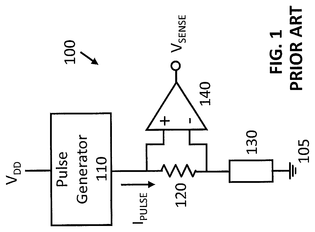
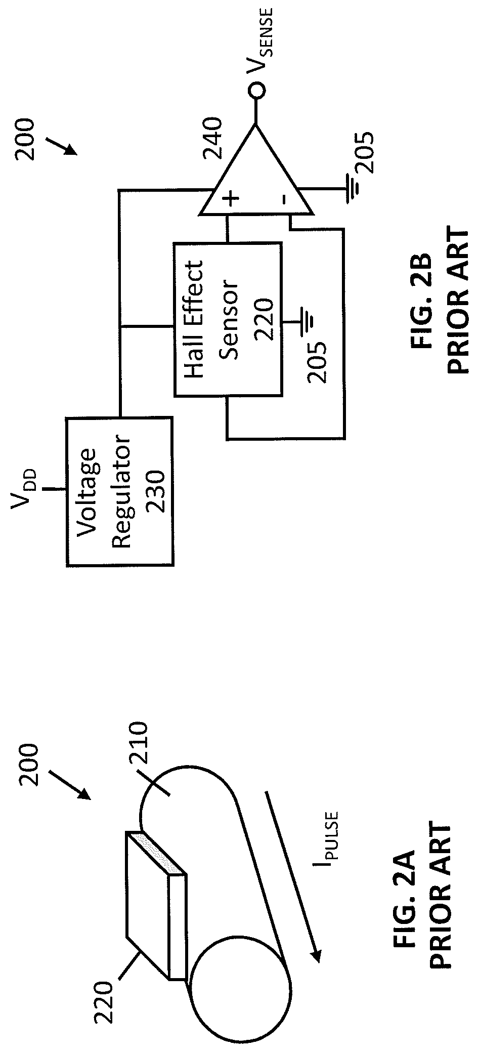
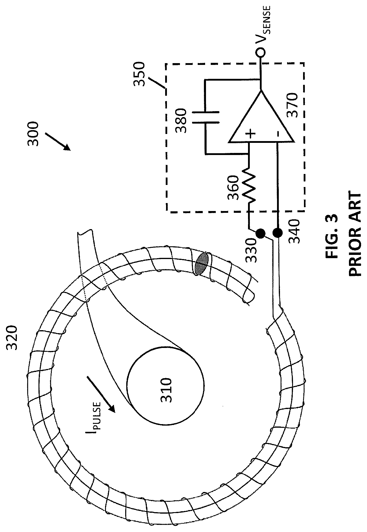
[0025]FIG. 4A shows a graph of a voltage output from a conventional current measurement circuit such as the circuits shown in FIGS. 1-3, and FIG. 4B shows the derivative of the voltage output from the conventional current measurement circuit. Graph 400 shows the output voltage VSENSE from a conventional current measurement circuit over time, where VSENSE is substantially proportional to the current pulse IPULSE ...


PUM


Abstract

A current measurement circuit for determining a start time tSTART, an end time tEND, and/or a peak time tMAX for a current pulse passing through a current conductor. The current measurement circuit comprises a pickup coil and a threshold crossing detector. The pickup coil generates a voltage VSENSE′ proportional to a magnetic field around the conductor, which is proportional to a change in current over time. The threshold crossing detector compares VSENSE′ and a threshold voltage and generates an output signal indicative of a transition time and whether a slope of VSENSE′ is positive or negative. The current measurement circuit can also comprise an integrator and a sample and hold circuit. The integrator integrates VSENSE′ over time and generates an integrated signal VSENSE. The sample and hold circuit compares VSENSE to tMAX and generates a second output signal which can be used to measure the pulse current.

Description

[0001]This application claims the benefit of U.S. Provisional Application No. 62 / 756,191, filed on Nov. 6, 2018, the entire disclosure of which is hereby incorporated by reference.BACKGROUND1. Field of the Invention[0002]The present invention relates generally to current measurement circuits based on magnetic field sensing, and more particularly to a current measurement circuit for determining a start time and an end time for a current pulse.2. Description of the Related Art[0003]In many applications for pulse current generators, the output current pulses must meet particular specifications such as precise start and end times and a maximum or minimum current value. For example, in a time-of-flight (ToF) light detection and ranging (lidar) system for an autonomous vehicle, a pulse current generator acts as a laser driver. The time delay between transmission of a laser pulse and detection of its reflection can be used to determine the distance between the laser and objects in the envi...

Claims


Application Information

Patent Timeline
Patent Type & Authority Applications(United States)
IPC IPC(8): G01R19/00G01R33/09
CPCG01R19/0092G01R33/063G01R33/093G01R33/028G01R15/181G01R29/02G01R19/0038G01R19/16566G01R29/027G01R19/0023
Inventor GLASER, JOHN S.DE ROOIJ, MICHAEL A.
Owner EFFICIENT POWER CONVERSION CORP
Why Eureka
Try Eureka