DC-DC converter and control method thereof

a converter and control method technology, applied in the direction of dc-dc conversion, power conversion systems, climate sustainability, etc., can solve the problem of not being able to prevent a backward current, and achieve the effect of reducing backward curren

Active Publication Date: 2007-04-26
TDK CORPARATION
View PDF5 Cites 28 Cited by
  • Summary
  • Abstract
  • Description
  • Claims
  • Application Information

AI Technical Summary

Benefits of technology

[0023] The present invention is made in view of the above-described conventional problems. An object of the present invention

Problems solved by technology

Therefore, the abnormal state detecting method disclose

Method used


Image

  • DC-DC converter and control method thereof
  • DC-DC converter and control method thereof
  • DC-DC converter and control method thereof

Examples


first embodiment

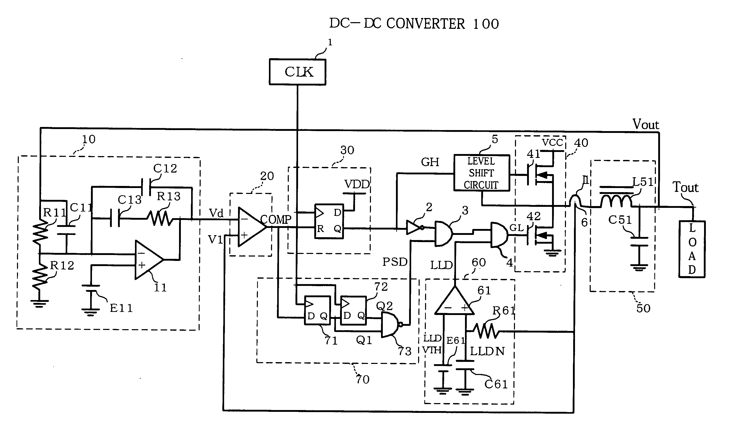
[0064] As shown in FIG. 1, a DC (direct current)-DC (direct current) converter 100 according to the present embodiment comprises a control circuit 10, a comparator 20, a D type flip flop circuit 30 (hereinafter referred to as D-FF 30), a switching circuit 40, a smoothing circuit 50, a light load detecting circuit 60, a pulse skipping detecting circuit 70, a clock circuit 1, a NOT circuit 2, an AND circuit 3, an AND circuit 4, a level shift circuit 5, and a load current detecting circuit 6.

[0065] The control circuit 10 comprises voltage dividing circuits (resistors) R11 and R12, a high-pass capacitor C11, an integrating circuit including an error amplifier 11, a high-pass capacitor C12, a capacitor C13 for integration, and a resistor R13, and a reference power source E11.

[0066] The output terminal Tout of the DC-DC converter 100 is connected to one end of the resistor R11. The other end of the resistor R11 is connected to one end of the resistor R12. The other end of the resistor R...

second embodiment

[0099] According to the first embodiment, the pulse skipping detecting circuit 70 is structured to operate in accordance with the same clock signal as the clock signal CLK supplied to the D-FF 30 (structured to operate synchronously). However, the pulse skipping detecting circuit 70 needs at least to be able to detect that the D-FF 30 maintains a low level signal without outputting the pulse signal, which should originally be output, for some time or longer (or that the D-FF 30 continues to be reset). In other words, the making of the pulse skipping circuit 70 is arbitrary, as long as it can directly or indirectly measure the period during which the outputting of the pulse signal is stopped.

[0100] For example, FIG. 3 shows an example of a DC-DC converter 200, which comprises a D-FF 71, a D-FF 72, and a pulse skipping detecting circuit 70 which operate in synchronization with a clock signal CLK2 independent from the clock signal CLK1 controlling the D-FF 30.

[0101] With this structu...


PUM


Abstract

A DC-DC converter has a switching circuit including switching elements at the high-side and at the low-side, an inductor connected to the output end of the switching circuit, a smoothing capacitor connected to the inductor, a switching control circuit for supplying a switching pulse to the switching elements, and a circuit. The circuit detects that a state that the switching element at the high side is switched off and the switching element at the low side is switched on is maintained for a predetermined period or longer. In this case, the circuit forcibly switches off the switching element at the low side.

Description

BACKGROUND OF THE INVENTION [0001] 1. Field of the Invention [0002] The present invention relates to a DC-DC converter and a control method thereof. Particularly, the present invention relates to a DC-DC converter which produces no backward current, which flows from a smoothing circuit to a synchronous rectifying circuit, when the load becomes light, and a control method thereof. [0003] 2. Description of the Related Art [0004] In a DC-DC converter, a switching circuit is switched on and off in response to a pulse signal, to intermittently supply a DC voltage to an inductance element. In some cases, such a DC-DC converter adopts a synchronous rectifying method of supplying a returning current, which flows into the inductance element while no electricity is supplied thereto, to the load through the switching element. [0005]FIG. 8 shows one example of circuit structure of an assumable DC (direct current)-DC (direct current) converter of a synchronous rectifying type. This DC-DC convert...

Claims


Application Information

Patent Timeline
IPC IPC(8): G05F1/00
CPCH02M1/32H02M3/1588Y02B70/1466Y02B70/10
Inventor IMAI, TAKAKAZUGOKITA, TAKEO
Owner TDK CORPARATION
Why Eureka
Try Eureka