Method to prevent anti-assist feature and side lobe from printing out

Inactive Publication Date: 2007-04-26
MACRONIX INT CO LTD
View PDF6 Cites 9 Cited by
  • Summary
  • Abstract
  • Description
  • Claims
  • Application Information

AI Technical Summary

Benefits of technology

[0008] Broadly speaking, the present invention fills this need by providing a photolithographic method that can prevent the anti-assist fea

Problems solved by technology

The reduced photo process window lowers the quality of the image produced on the photoresist layer, and makes a photolithographic process more difficult.
The side lobe phenomena result in undesired f

Method used


Image

  • Method to prevent anti-assist feature and side lobe from printing out
  • Method to prevent anti-assist feature and side lobe from printing out
  • Method to prevent anti-assist feature and side lobe from printing out

Examples


Example

[0018] Reference is made in detail to embodiments of the invention. While the invention is described in conjunction with the embodiments, the invention is not intended to be limited by these embodiments. On the contrary, the invention is intended to cover alternatives, modifications and equivalents, which may be included within the spirit and scope of the invention as defined by the appended claims. Furthermore, in the following detailed description of the invention, numerous specific details are set forth in order to provide a thorough understanding of the invention. However, as is obvious to one ordinarily skilled in the art, the invention may be practiced without these specific details. In other instances, well-known methods, procedures, components, and circuits have not been described in detail so that aspects of the invention will not be obscured.

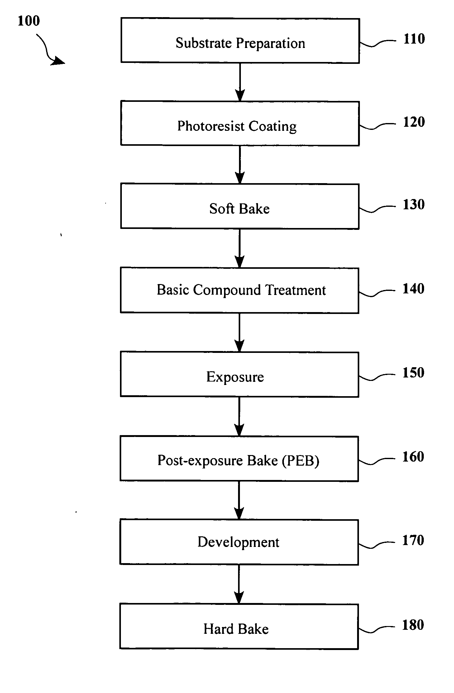
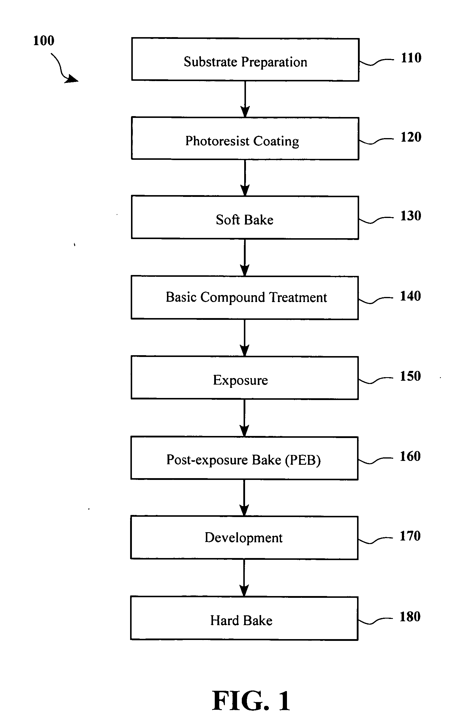
[0019] Referring initially to FIG. 1, a flowchart 100 is shown illustrating the steps of a photolithographic process in accordance w...


PUM


Abstract

A method for forming photo patterns on a photoresist layer is disclosed. A photoresist layer is formed over a substrate. The photoresist layer is then treated with a basic compound and is exposed. The photoresist layer can be treated with a basic compound first, and then exposed. The photoresist layer can also be exposed first, and then treated with a basic compound. The basic compound treatment for the photoresist layer can be performed by using a basic compound in the form of liquid or gas, and it can also be performed by forming a basic compound layer over the photoresist layer. The basic compound can be an amine compound. The mask used during an exposure may contain anti-assist feature (AF), and it can also be a half tone phase shift mask (HTPSM). Thus, the method can prevent anti-AF and side lobe from printing out.

Description

BACKGROUND OF THE INVENTION [0001] 1. Field of the Invention [0002] The present invention relates generally to photolithography, and more particularly, to a treatment method that is capable of reducing or eliminating the anti-assist feature and side lobe printing out phenomena. [0003] 2. Description of the Related Art [0004] Photolithography is a critical and indispensable fabrication technique that is used to transfer integrated circuit (IC) layout patterns through a mask onto predefined locations on a semiconductor substrate. In a conventional photolithographic process, the substrate is first coated with a photoresist layer that is made from a material sensitive to light radiation, such as deep ultraviolet (DUV) light. Next, the photoresist layer applied to the substrate surface undergoes a soft bake to drive off most of the solvent in the photoresist layer. Then, the substrate is exposed to light through a mask that contains the pattern corresponding to the features at a layer of...

Claims


Application Information

Patent Timeline
IPC IPC(8): G03F7/26
CPCG03F1/144G03F1/32G03F7/11G03F7/168G03F1/36
Inventor YANG, CHIN CHENG
Owner MACRONIX INT CO LTD
Why Eureka
Try Eureka