
Manufacturing system

a manufacturing system and assembly unit technology, applied in the field of manufacturing systems, can solve the problems of increasing the working radius of workers, occupying a lot of space, and increasing the length of assembly units, so as to improve productivity, increase and decrease production, and work small space

Inactive Publication Date: 2007-05-03
SAMSUNG ELECTRONICS CO LTD
View PDF0 Cites 9 Cited by
  • Summary
  • Abstract
  • Description
  • Claims
  • Application Information

AI Technical Summary

Benefits of technology

[0012] An aspect of exemplary embodiments of the present invention is to address at least the above problems and / or disadvantages and to provide at least the advantages described below. Accordingly, an aspect of exemplary embodiments of the present invention is to provide a manufacturing system which improves productivity with a small work space and work force coping with an increase and decrease of production, and a variety of products.
[0013] Also, it is another aspect of exemplary embodiments of the present invention to provide a manufacturing system in which a moving unit such as a conveyor is reduced, a pallet supporting a product is removed, which is less affected by vibrations or shocks caused when moving the product.

Problems solved by technology

Accordingly, the length of an assembly unit becomes longer, thereby taking much space due to the keeping table and the worktable, and widening a working radius of a worker.
Also, it is difficult to use the space efficiently.
Further, since the conventional manufacturing system is arranged in a straight line or in a -shaped line to perform various tests in the test process, the space efficiency becomes lowered and its configuration becomes complicated for power and signal supplying.
Furthermore, the monitor device may be affected by vibrations, noises and shocks due to a long moving line.

Method used


Image

  • Manufacturing system
  • Manufacturing system
  • Manufacturing system

Examples


Embodiment Construction

[0054] The matters defined in the description such as a detailed construction and elements are provided to assist in a comprehensive understanding of exemplary embodiments of the invention. Accordingly, those of ordinary skill in the art will recognize that various changes and modifications of the embodiments described herein can be made without departing from the scope and spirit of the invention. Also, descriptions of well-known functions and constructions are omitted for clarity and conciseness.

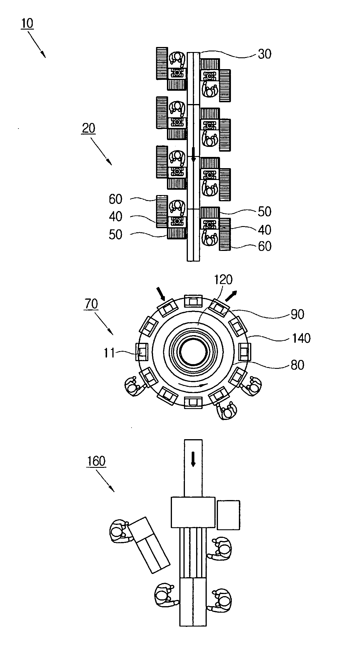
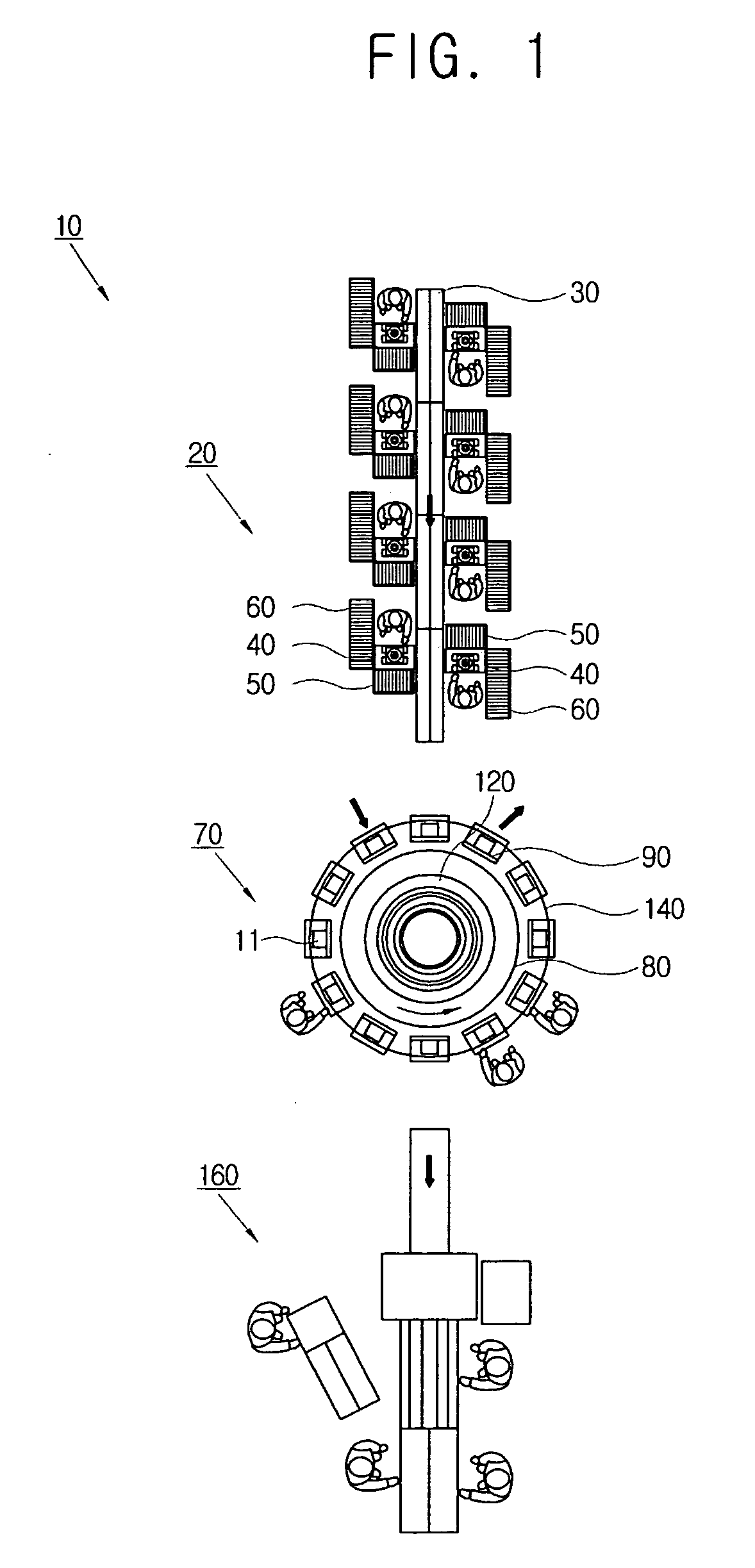
[0055] As shown in FIG. 1, a monitor device manufacturing system 10 according to an exemplary embodiment of the present invention comprises an assembly unit 20 which assembles components of a monitor device 11; a test unit 70 which tests and adjusts the assembled monitor device 11; and a packaging unit 160 which packages the monitor device 11 that has passed the test unit 70. The assembly unit 20, the test unit 70 and the packaging unit 160 of the monitor device manufacturing system 10 ar...


PUM

PropertyMeasurementUnit
sizeaaaaaaaaaa
diameteraaaaaaaaaa
diameteraaaaaaaaaa

Abstract

A manufacturing system comprising an assembly unit for assembling components of a product, a test unit for testing the assembled product and a packaging unit for packaging the product that has passed the test unit is provided. The assembly unit comprises a moving unit, a worktable adjacent to the moving unit, first and second auxiliary worktables and a caster provided on a lower portion thereof, and a rotator to rotate one of the first and second auxiliary worktables with respect to the other within an predetermined angle. The test unit comprises a rotation table, a base for supporting the rotation table, a driving unit provided on the base, and a plurality of jigs disposed on the rotation table at a predetermined interval. Thus, the manufacturing system provides improved productivity with a small work space and work force coping with an increase and decrease of production, and a variety of products.

Description

CROSS-REFERENCE TO RELATED APPLICATIONS [0001] This application claims the benefit under 35 U.S.C. § 119(a) of Korean Patent Application No. 2005-0102990, filed on Oct. 31, 2005, in the Korean Intellectual Property Office, the entire disclosure of which is hereby incorporated by reference. BACKGROUND OF THE INVENTION [0002] 1. Field of the Invention [0003] The present invention relates to a manufacturing system. More particularly, the present invention relates to a manufacturing system which comprises an assembly unit, a test unit and a packaging unit for products. [0004] 2. Description of the Related Art [0005] Generally, products are manufactured through various processes before being supplied to a customer. A manufacturing system typically comprises a component manufacturing process, an assembly process which assembles components, a test process for an assembled product, and a packaging process in which the products are packaged. [0006] Here, the product may comprise electronic a...

Claims


Application Information

Patent Timeline
Patent Type & Authority Applications(United States)
IPC IPC(8): B23P21/00
CPCB23P21/006Y10T29/53022Y10T29/5191Y10T29/5313Y10T29/53048G06Q10/06G06Q50/04
Inventor LEE, GAP-SOOLIM, JOUNG-SUULEE, KWAN-HEEKIM, PAN-SUJU, YOUNG-MOKKIM, JEONG-KYU
Owner SAMSUNG ELECTRONICS CO LTD
Learn More