Cooling apparatus and cooling method for electric storage device of electrically powered vehicle

a technology of electric storage device and cooling apparatus, which is applied in the direction of domestic cooling apparatus, lighting and heating apparatus, cell components, etc., can solve the problems of large heat generated by driving the motor or charging it, quick cooling of the condenser, etc., and achieve the effect of reducing the electric storage device, increasing the flow rate of cooling air, and improving cooling performan

Inactive Publication Date: 2007-05-03
HONDA MOTOR CO LTD
View PDF14 Cites 10 Cited by
  • Summary
  • Abstract
  • Description
  • Claims
  • Application Information

AI Technical Summary

Benefits of technology

[0025] In this case, when the cooler is in operation, if the temperature of the electric storage device increases and exceeds the first predetermined value and if the insolation intensity exceeds the third predetermined value, the controller increases the number of rotations of the fan, and thereby increasing the flow rate of ...

Problems solved by technology

Since the electrically powered vehicles use the high-voltage condensers, the amount of heat generated by driving the motor or by charging it is large.
However, for example, when ambient temperature outside the vehicle is high or when insolation intensity insi...

Method used


Image

  • Cooling apparatus and cooling method for electric storage device of electrically powered vehicle
  • Cooling apparatus and cooling method for electric storage device of electrically powered vehicle
  • Cooling apparatus and cooling method for electric storage device of electrically powered vehicle

Examples


Embodiment Construction

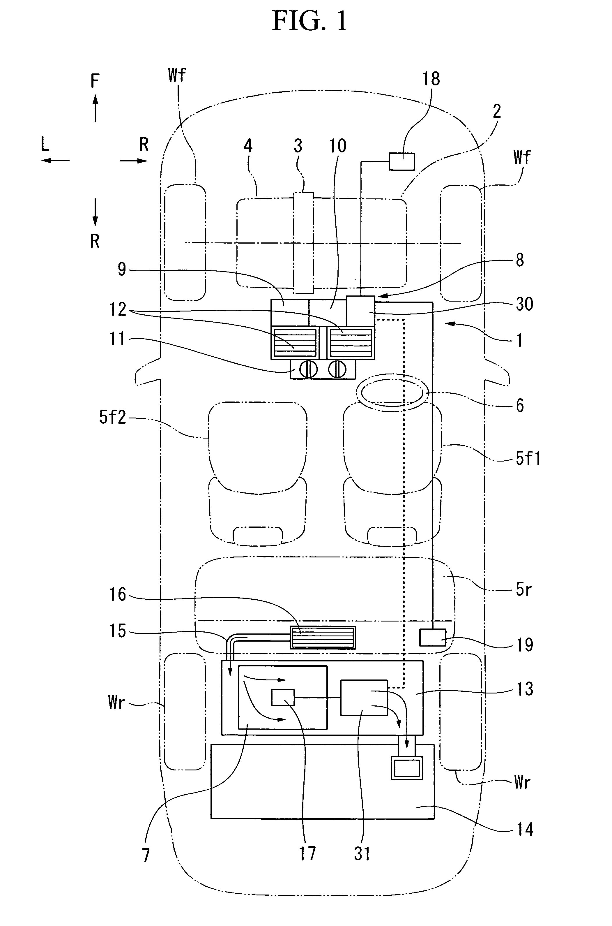
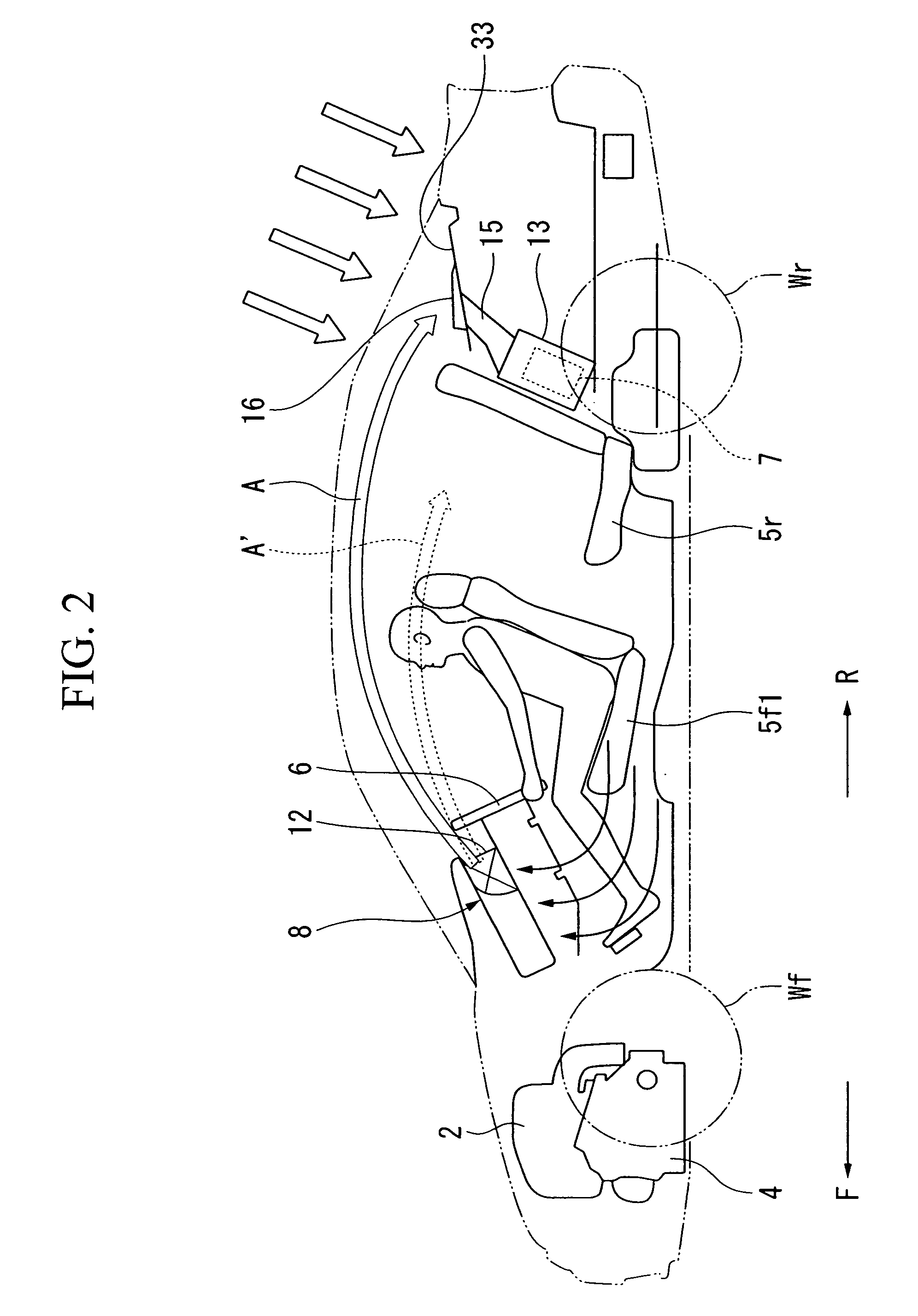
[0029] One embodiment of a cooling apparatus for a condenser of an electrically powered vehicle according to the present invention will be explained below with reference to the drawings. In the following explanation, directions such as forward, backward, left, and right correspond, if there is no particular description, to directions of the vehicle. Furthermore, in the drawings, an arrow F indicates a forward direction, an arrow R indicates a rearward direction, an allow L indicates a left direction, and an allow R indicates a right direction.

[0030]FIGS. 1 and 2 show a hybrid vehicle (an electrically powered vehicle) equipped with a cooling apparatus for a condenser of an electrically powered vehicle 1 of the present embodiment. This hybrid vehicle is so-called a parallel type in which an engine 2 and a motor generator 3 (a vehicle driving motor) are connected in series, and driving powers of these are transferred to driving wheels (for example, front wheels Wf) through a transmiss...


PUM


Abstract

This cooling apparatus for a condenser of an electrically powered vehicle including a vehicle driving motor to which an electrical power is supplied from a condenser through an inverter, includes: a cooler including a fan which sends a cooling air into a cabin interior; a suction port which is open to the cabin interior so as to suck the cooling air and supplies the cooling air toward the condenser; and a controller which increases the number of rotations of the fan when the fan is in operation and a temperature of the condenser exceeds a first predetermined value.

Description

BACKGROUND OF THE INVENTION [0001] Priority is claimed on Japanese Patent Application No. 2005-314198, filed Oct. 28, 2005, the contents of which are incorporated herein by reference. [0002] 1. Field of the Invention [0003] The present invention relates to a cooling apparatus and a cooling method for an electric storage device of electrically powered vehicles such as a hybrid vehicle and an electric vehicle, equipped with a vehicle driving motor to which electrical power is supplied from the electric storage devices such as a battery and a capacitor through an inverter. In especially, the present invention relates to a cooling apparatus and a cooling method for an electric storage device of an electrically powered vehicle, which cools the electric storage device by utilizing cooling air supplied into a cabin interior from a cooler. [0004] 2. Description of the Related Art [0005] Electrically powered vehicles such as a hybrid vehicle and an electric vehicle are provided with a high-v...

Claims


Application Information

Patent Timeline
IPC IPC(8): B60H3/00F25D23/12B60H1/32H01M2/10H01M10/60
CPCB60H1/00278B60H2001/003H01M10/5004H01M10/5016H01M10/5022H01M10/5024H01M10/5067H01M10/5073H01M10/5095B60L50/40B60L58/26H01M10/613H01M10/625H01M10/633H01M10/635H01M10/6563H01M10/6566H01M10/663Y02E60/10Y02T10/70
Inventor TSUNEISHI, JUNYATAKAHASHI, YOSHIAKI
Owner HONDA MOTOR CO LTD
Why Eureka
Try Eureka