Method and apparatus for non-destructive testing of concrete structures

a concrete structure and non-destructive testing technology, applied in the direction of instruments, magnetic property measurements, and analysis of solids using sonic/ultrasonic/infrasonic waves. the problem of difficult to measure with a dedicated probe for transverse waves is particularly troublesome, and the sonic velocity ratio cannot be immediately obtained on si

Inactive Publication Date: 2007-05-03
FUJIMITSU ENG
View PDF9 Cites 22 Cited by
  • Summary
  • Abstract
  • Description
  • Claims
  • Application Information

AI Technical Summary

Benefits of technology

[0023] The reason is that moving the transmission probe prevents the ultrasonic pulses immediately after coming into incidence from keeping on hitting against any obstacle, moving the reception probe pre

Problems solved by technology

This means a problem that the sonic velocity ratio cannot be immediately obtained on site but takes a very long time to determine.
Measurement with a dedic

Method used


Image

  • Method and apparatus for non-destructive testing of concrete structures
  • Method and apparatus for non-destructive testing of concrete structures
  • Method and apparatus for non-destructive testing of concrete structures

Examples


Embodiment Construction

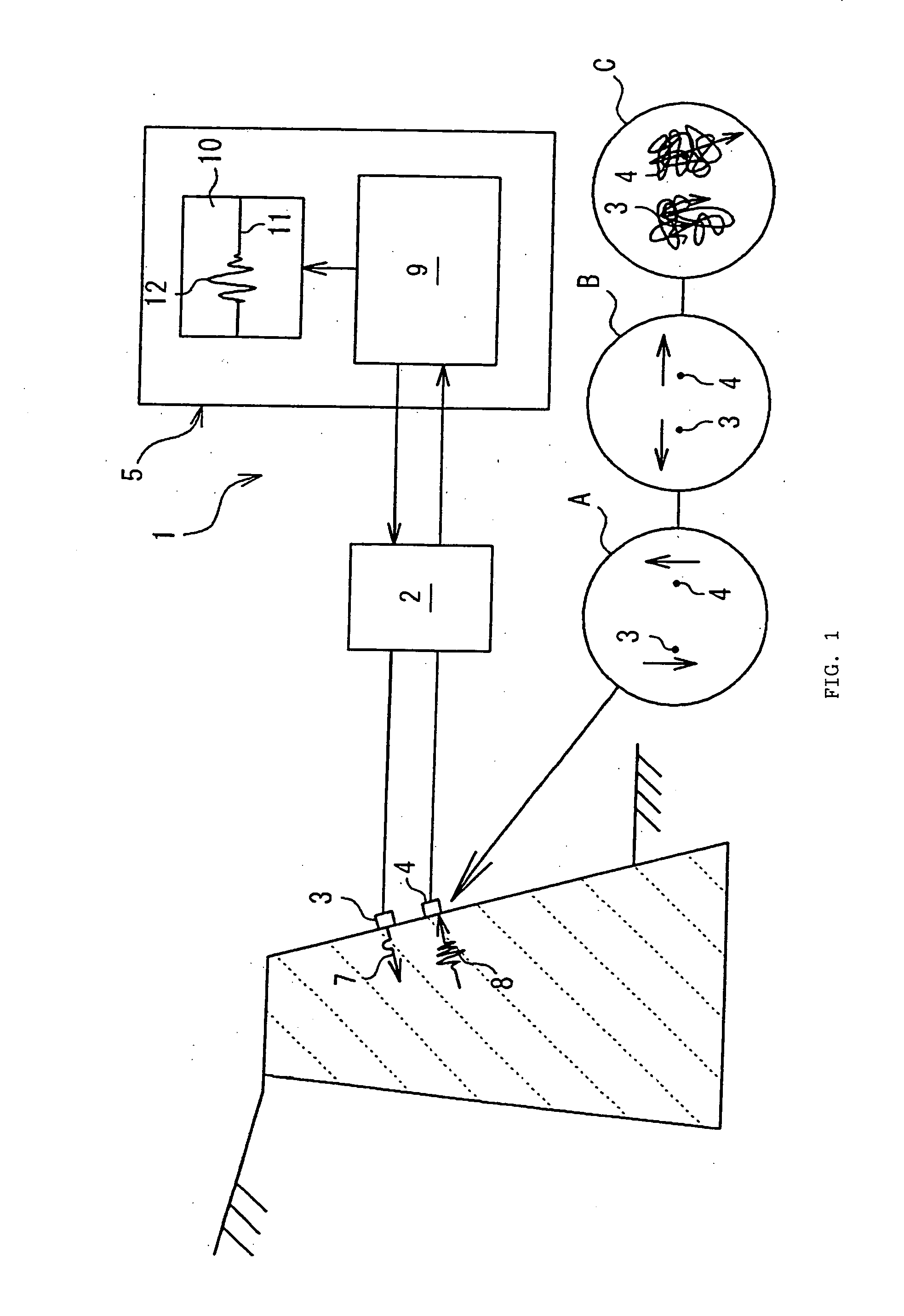
[0031]FIG. 1 schematically shows the configuration of a non-destructive testing apparatus, which is an embodiment of the present invention. As shown in this drawing, a non-destructive testing apparatus 1 comprises a non-destructive testing apparatus body 2, a dedicated transmission probe (pulsar) 3 for longitudinal waves connected to this testing apparatus body 2, a dedicated reception probe (receiver) 4 for longitudinal waves connected to the testing apparatus body 2 separately from this transmission probe 3, and a data processing apparatus 5, composed of a portable personal computer or the like, connected to the testing apparatus body 2.

[0032] Of these elements, the transmission probe 3 transmits ultrasonic pulses 7 into a concrete structure, which may be a sheathing revetment, a weir or the like. The transmission probe 3 is configured by stacking acoustic matching layers comprising epoxy resin or the like over a piezoelectric element comprising an electro-acoustic conversion ele...


PUM


Abstract

An ultrasonic pulse is applied from a transmission probe for longitudinal waves kept in contact with the external surface of a concrete structure into the interior of the structure, and a reflected wave returning after being reflected by the boundary face of the concrete structure is detected with a reception probe for longitudinal waves kept in contact with the external surface of a concrete structure. As the first peak recognized in the waveform of the reflected wave represents the reaching time T1 of the bottom face echo which has undergone no mode conversion, and the subsequently obtained second peak, in about 1.3 to 1.7 times when first peak appeared, represents the reaching time T2 of the delayed echo which has undergone a mode conversion, the sonic velocity ratio R of longitudinal wave to transverse wave is calculated from these reaching times T1 and T2. Then, object physical quantities corresponding to the sonic velocity ratio R are figured out from correlations known in advance regarding the concrete structure between the sonic velocity ratio R and object physical quantities.

Description

BACKGROUND OF THE INVENTION [0001] 1. Field of the Invention [0002] The present invention relates to a non-destructive testing method and apparatus for measuring object physical quantities of a concrete structure, such as compressive strength thereof and progress of alkali aggregate reaction therein, in a non-destructive way. [0003] 2. Description of the Related Art [0004] Concrete structures are subject to early deterioration due to such causes as insufficient compressive strength ensuing from faults in work execution, salt damage and alkali aggregate reaction, and such structures are measured by various methods to detect any such defect they may involve. Among these methods for diagnosing concrete structures, ultrasonic non-destructive testing is given attention for its quickness and low cost. [0005] One example of method to measure the progress of alkali aggregate reaction in concrete structures by ultrasonic probing is disclosed in Japanese Patent Application Laid-open No. 2003-...

Claims


Application Information

Patent Timeline
IPC IPC(8): G01N29/04
CPCG01N29/07G01N29/449G01N33/383G01N2203/0075G01N2291/0232G01N2291/02827G01N2291/0421G01N2291/0422G01N2291/0428G01N2291/044G01N2291/102
Inventor HARA, TOORU
Owner FUJIMITSU ENG
Why Eureka
Try Eureka