
Eureka
For R&D, Eureka makes reading and utilizing patents & technical documents easy.
Eureka AIR
Designed for self-driven R&D workflows. Generate viable solutions, solve complex R&D challenges, empower your innovation with AI.

Eureka Materials
Designed for material experts only. Revolutionize your material R&D, from search, analyze, to developing new materials.

TechResearch
Generate reliable direction feasibility study reports for your R&D in just a few steps.

TechSeek
Discover and master advanced knowledge NOW. Basics, ideas, possibilities, all at once.

TechMind
As an expert in R&D Theories, TechMind can generates customized viable solutions instantly.

TechRisk
Analyze your overall solution with one click, know your potential R&D risks in advance.

TechMonitor
Get weekly tech updates, stay abreast of the latest tech innovations and key insights.
Method and apparatus for measuring cryogenic flow
- Summary
- Abstract
- Description
- Claims
- Application Information
AI Technical Summary
Problems solved by technology
Method used
Image

Examples
Embodiment Construction
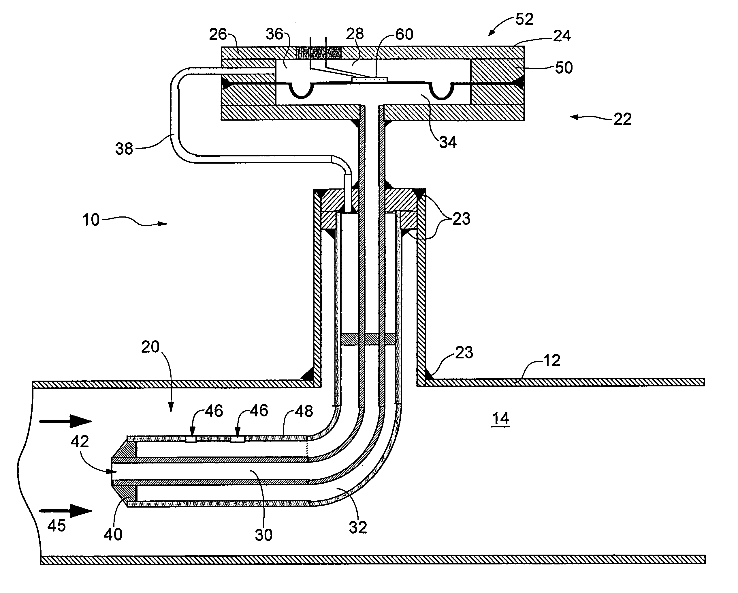
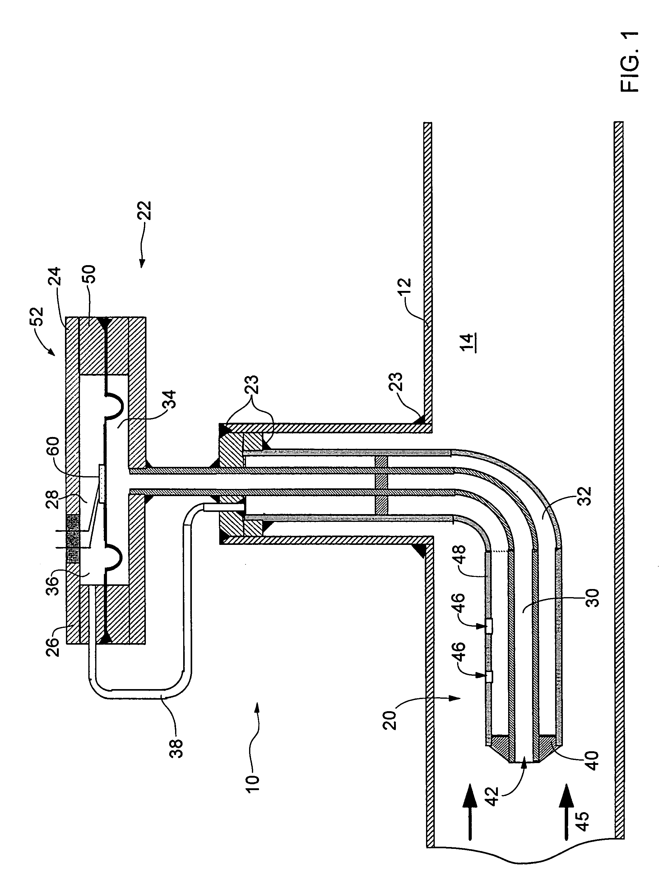
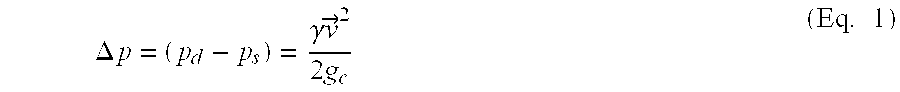
[0008] The present invention is directed to a method and apparatus for measuring a mass flow rate of a cryogenic fluid. The method and apparatus of the present invention measures the pressure difference between a static or ambient pressure and a dynamic or total pressure in a cryogenic fluid stream to calculate the mass flow rate of the cryogenic fluid. The pressure difference (Δp) between the static pressure (ps) and the total pressure measured at a front or lead end of the apparatus (pd) is equal to the change in kinetic energy of the cryogenic fluid stream, characterized by the following formula: Δ p=(pd-ps)=γ v→22gc(Eq. 1)
[0009] wherein γ is equal to a specific weight of the cryogenic fluid; {right arrow over (v)} is the free stream velocity; and gc is the gravitational acceleration. Thus, the mass flow rate of the cryogenic fluid is calculated using the following equation:
m=Af√{square root over (2gcΔpγ)} (Eq. 2)
[0010] wherein Af is the free stream cross-sectional area...
PUM
 Abstract
Description
Claims
Application Information
 - R&D Engineer
- R&D Manager
- IP Professional
- Industry Leading Data Capabilities
- Powerful AI technology
- Patent DNA Extraction
Browse by: Latest US Patents, China's latest patents, Technical Efficacy Thesaurus, Application Domain, Technology Topic, Popular Technical Reports.
© 2024 PatSnap. All rights reserved.Legal|Privacy policy|Modern Slavery Act Transparency Statement|Sitemap|About US| Contact US: help@patsnap.com