Assembly fixture and method for machining injection mold tooling

a technology of injection mold and assembly fixture, which is applied in the field of assembly fixture and method for machining injection mold tooling, can solve the problems of machining the entire moveable mold half of the mold, and achieve the effects of easy and economical fabrication, long life in operation, and simple and inexpensiv

Inactive Publication Date: 2007-05-03
NOKIA CORP
View PDF1 Cites 7 Cited by
  • Summary
  • Abstract
  • Description
  • Claims
  • Application Information

AI Technical Summary

Benefits of technology

[0004] It is also an object of the present invention to provide a simple and inexpensive means and method of machining injection mold tooling.
[0005] It a further object to provide such an assembly fixture which may be readily and economically fabricated and will enjoy a long life in operation.
[0006] It has now been found that the foregoing and related objects can be readily attained in an assembly fixture for use in holding a moveable mold half insert assembly in its correct working position and orientation for spark eroding a final geometric form onto the moveable mold half insert assembly. The assembly fixture includes a base and an upstanding structure mounted on the base for supporting the moveable mold half insert assembly and defining a cavity into which a portion of the moveable mold half insert assembly extends.

Problems solved by technology

However, the machining of the entire moveable mold half of the mold requires a large electro discharge machine.

Method used


Image

  • Assembly fixture and method for machining injection mold tooling
  • Assembly fixture and method for machining injection mold tooling
  • Assembly fixture and method for machining injection mold tooling

Examples


Embodiment Construction

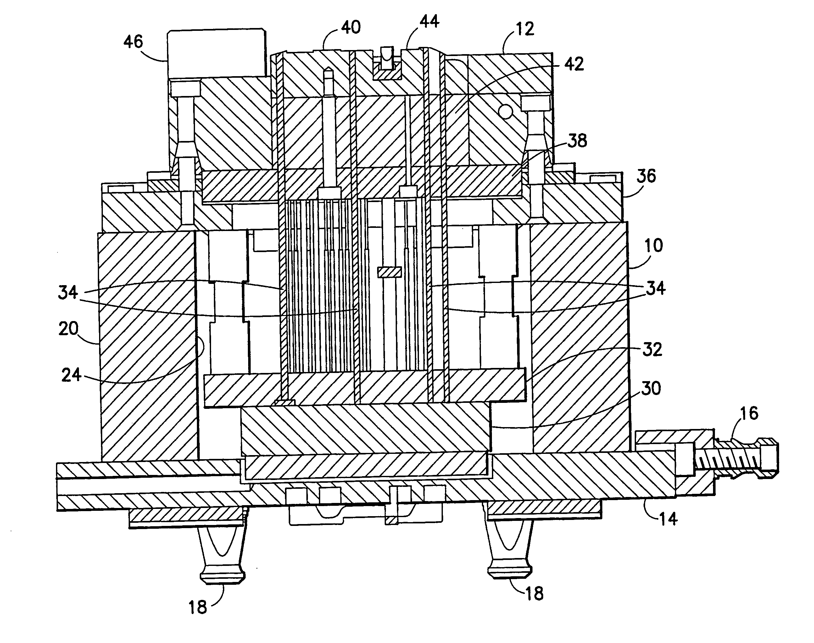
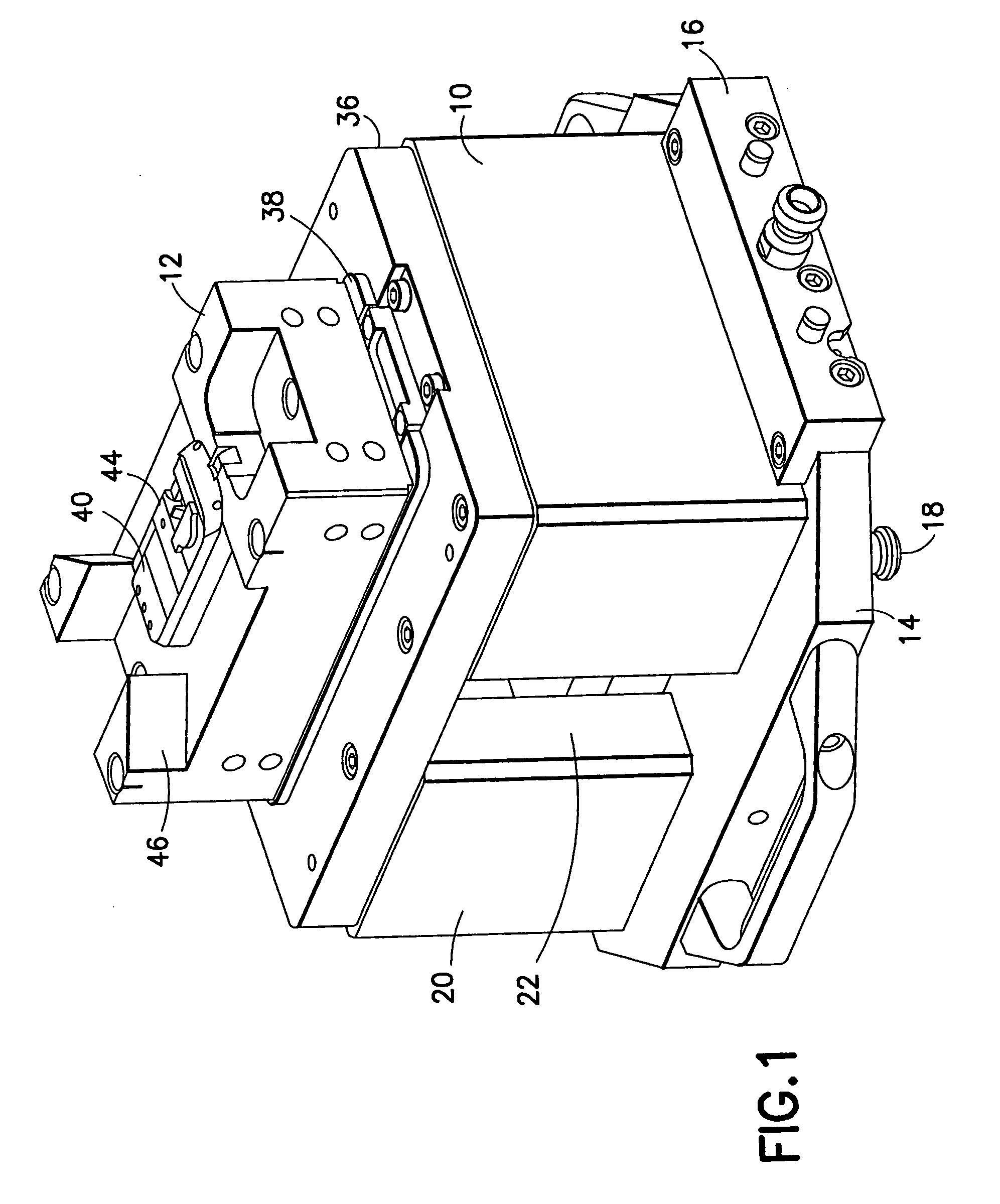
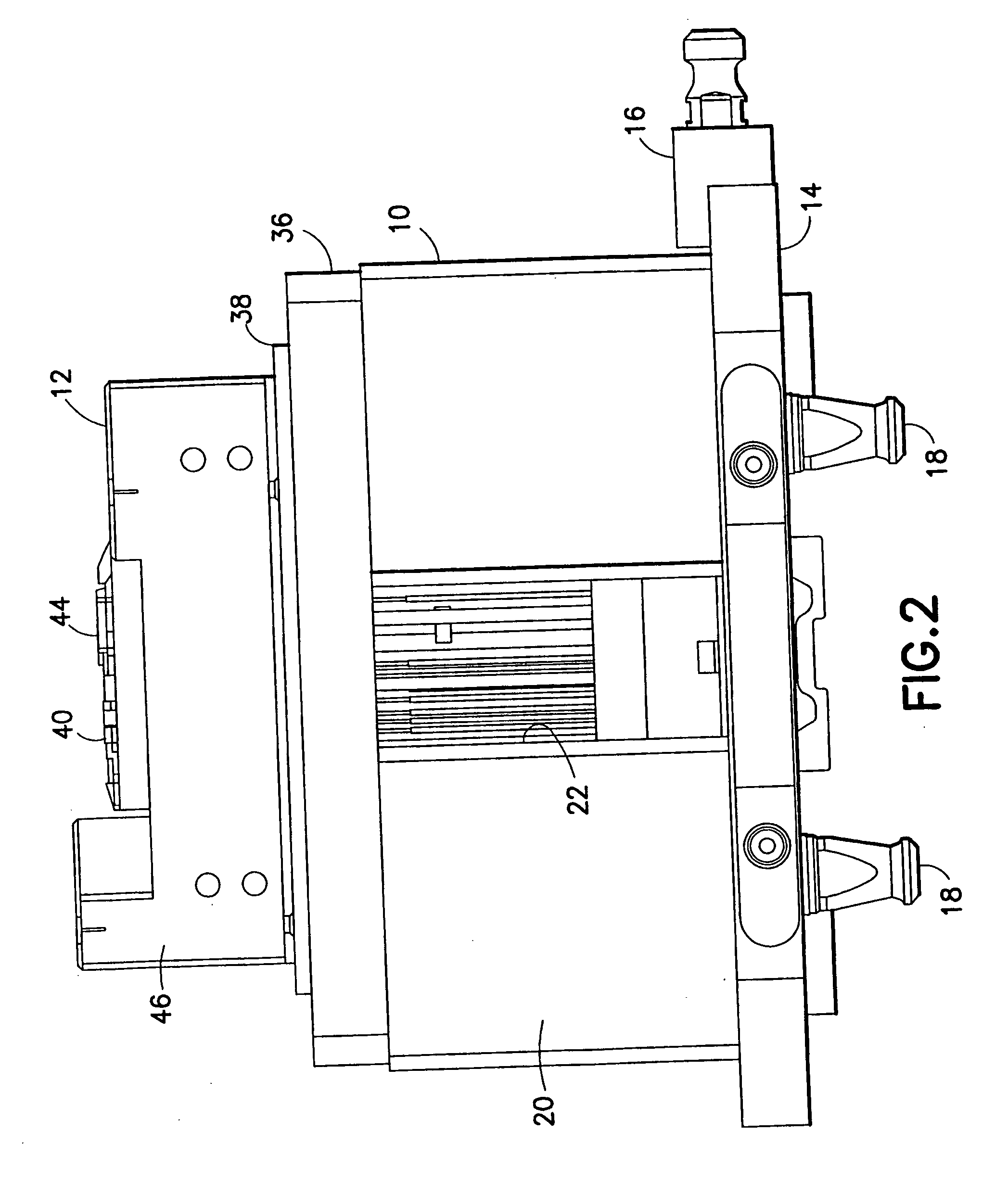
[0015] Turning now to the drawings and considering the invention in further detail, a moveable mold half assembly fixture 10 is illustrated therein and is designed for holding a moveable mold half insert assembly 12 during an electro discharge machining process. The moveable mold half assembly which is illustrated is used in the manufacture of components for cellular phones such as device covers for cellular phones. The moveable mold half assembly fixture 10 has a base plate 14 manufactured by Erowa System Technolgien GmbH of Cadolzburg, Germany. At one end, the base plate 14 is provided with a robot handling component 16 which allows a robot (not shown) to pick up the moveable mold half assembly fixture 10 and moveable mold half insert assembly 12 and place them in the electro discharge machine (not shown). The base plate 14 also has spaced apart measuring machine alignment components 18 extending from the bottom side thereof to permit the moveable mold half assembly fixture 10 and...


PUM

PropertyMeasurementUnit
angleaaaaaaaaaa

Abstract

An assembly fixture is used to hold the moveable mold half insert assembly (e.g. the insert, cores, lifters, ejector pins, etc.) in its correct working position and orientation. To spark erode the final geometric form onto a moveable mold half insert assembly, the assembly fixture can be placed in an electro or electrical discharge machine (EDM) with the moveable mold half insert assembly therein.

Description

TECHNICAL FIELD [0001] The present invention relates generally to injection molding and deals more particularly with an assembly fixture and method for machining injection mold tooling. BACKGROUND OF THE INVENTION [0002] It is known in plastic injection molding that the moveable mold half insert assembly (comprised of the insert, cores, lifters and ejector pins) assembled onto the mold base forms the moveable mold half of the mold. To spark erode the final geometric form onto the moveable mold half insert assembly, this moveable mold half of the mold can be placed in an electro or electrical discharge machine (EDM) with the moveable mold half insert assembly (comprised of the insert, cores, lifters and ejector pins) in its correct working position and orientation on the mold base. However, the machining of the entire moveable mold half of the mold requires a large electro discharge machine. Accordingly, it would be a great advantage to provide a fixture which could hold the moveable...

Claims


Application Information

Patent Timeline
Patent Type & Authority Applications(United States)
IPC IPC(8): B23H9/12B23H1/00
CPCB23H9/00B23H11/003
Inventor DREES, GUIDODREES, RALFMEINERT, HEINRICHGERBER, MARTINGREBER, ERICHBERNET, GUIDO
Owner NOKIA CORP
Why Eureka
Try Eureka