Hydraulic control valve for drip hoses

a technology of hydraulic control valve and drip hose, which is applied in the field of valves, can solve problems such as water was

Inactive Publication Date: 2007-05-03
KIM CHOON IL
View PDF8 Cites 36 Cited by
  • Summary
  • Abstract
  • Description
  • Claims
  • Application Information

AI Technical Summary

Benefits of technology

[0005] Accordingly, the present invention has been made keeping in mind the above problems occurring in the prior art, and an object of the present invention is to provide a hydraulic control valve for drip hoses, capable of appropriately controlling a water pressure, prior to feeding high-pressure water of a water pump to a drip hose, thus preventing the drip hose from being damaged.

Problems solved by technology

However, the cultivation method with drip irrigation system has a problem in that water injection holes may be torn or water may be dispersed when high-pressure water is supplied to the drip hoses, thus causing a waste of water.

Method used


Image

  • Hydraulic control valve for drip hoses
  • Hydraulic control valve for drip hoses
  • Hydraulic control valve for drip hoses

Examples


first embodiment

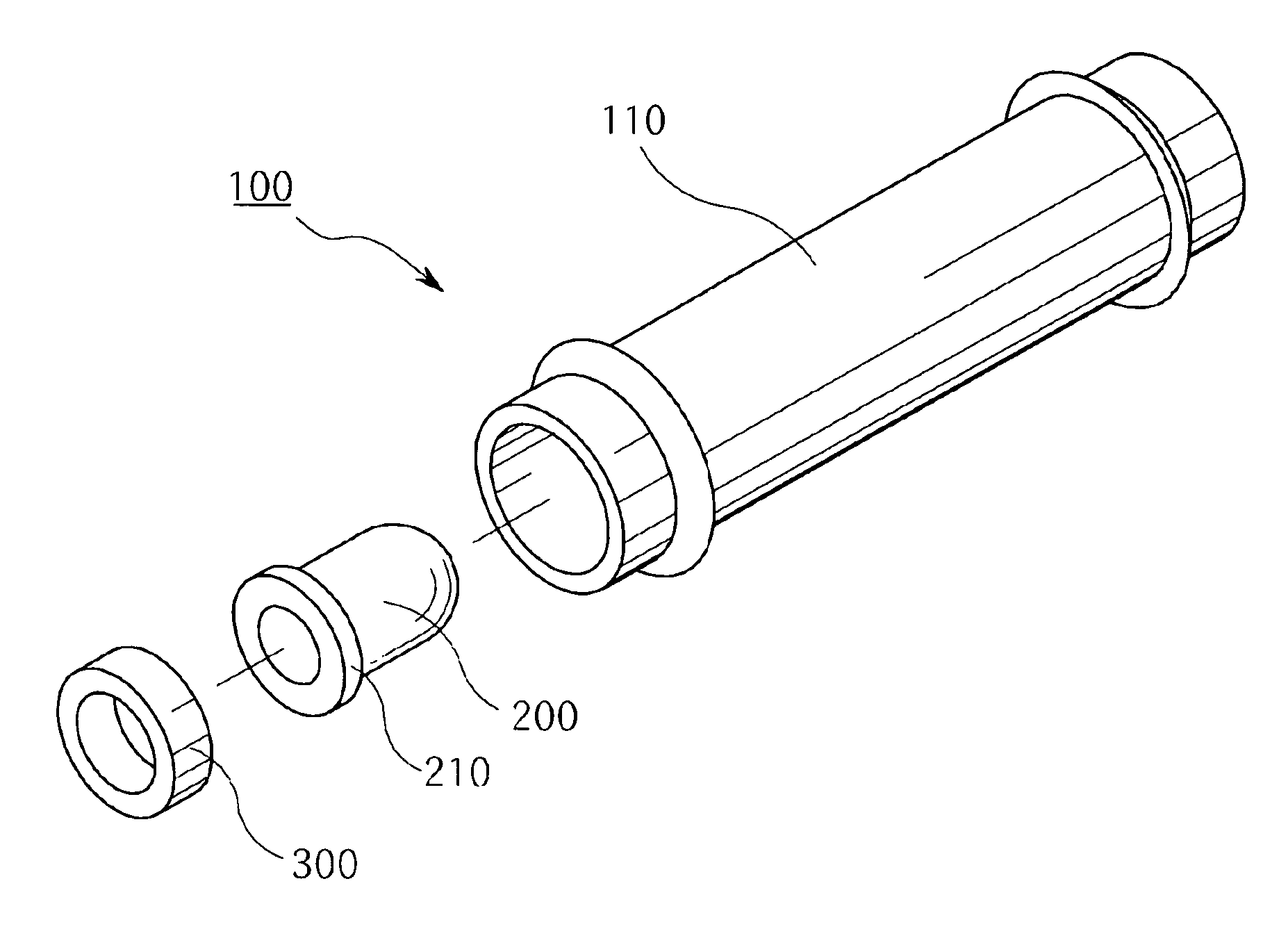
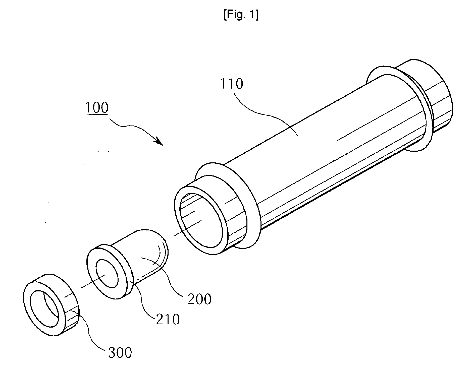
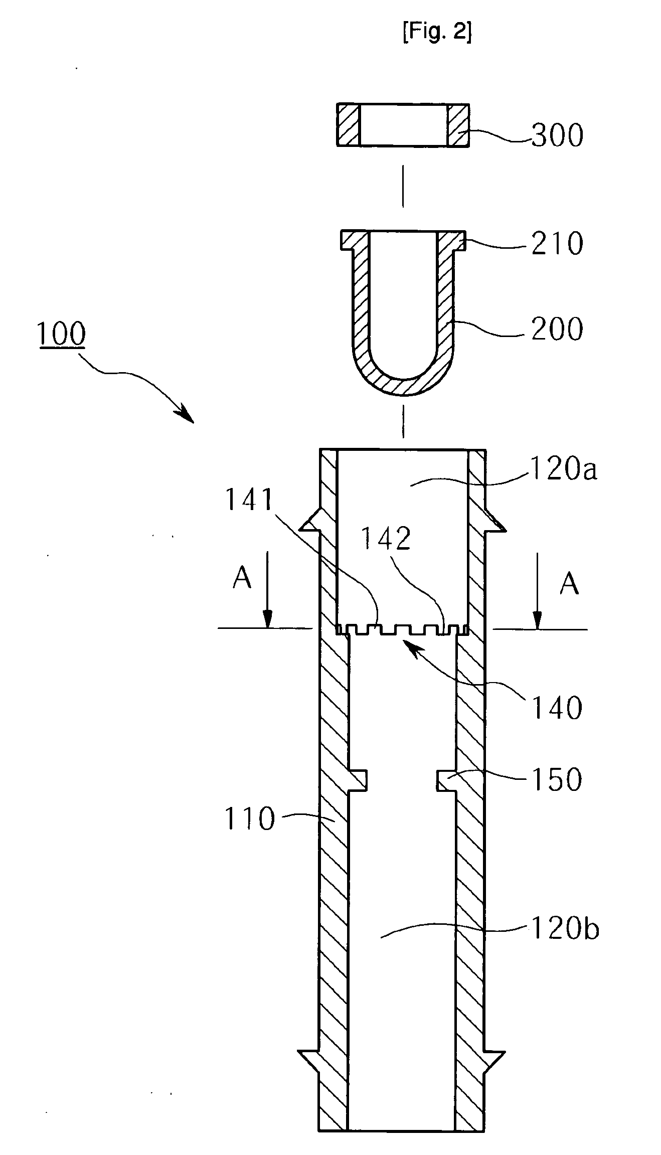
[0021] As shown in FIGS. 1 through 4, a hydraulic control valve 100 according to the present invention, includes a hose connector 110 clamped at opposite ends thereof to an end of a branch hose H / S and an end of a drip hose H / N, respectively. A water supply path is defined in the hose connector 110, and includes a larger-diameter path 120a having a stepped seat and a smaller-diameter path 120b.

[0022] In this case, the stepped seat is manufactured in a form of an uneven seat 140 having a plurality of projections 141 and depressions 142 that are alternately arranged on an upper surface of the uneven seat 140. The hydraulic control valve 100 further includes a U-shaped flexible cup 200 and a support ring 300. The U-shaped flexible cup 200 is opened at a first end thereof. A flange 210 is outwardly protruded from an edge of the U-shaped flexible cup 200, and is stopped by the uneven seat 140 so that the U-shaped flexible cup 200 is fitted into the smaller-diameter path 120b while an ou...

second embodiment

[0030] The operation of the hydraulic control valve is as follows. That is, as shown in FIG. 12, water is fed from the branch hose H / S through the water supply path 320 of the holder 310 into the U-shaped flexible cup 200.

[0031] When fed water has a low pressure, the U-shaped flexible cup 200 is not expanded outward, thus preventing the flow of water.

[0032] Meanwhile, as shown in FIG. 13, when fed water has a high pressure, the U-shaped flexible cup 200 is expanded outward, and water flows backward through a gap between an outer surface of the holder 310 and the U-shaped flexible cup 200. Thus, the water flows along the depressions 142 of the uneven seat 140 and the grooves 143 which are longitudinally arranged to be aligned with the depressions 142.

[0033] The hydraulic control valve according to the second embodiment can be utilized at a space where the water supply is allowed only when water pressure is relatively high.


PUM


Abstract

The object of this invention is to provide a hydraulic control valve for drip hoses, which controls a flow of water according to a water pressure, thus keeping a pressure of water fed to a drip hose constant. The hydraulic control valve includes a hose connector (110) clamped at opposite ends thereof to a branch hose (H/S) and a drip hose (H/N), a water supply path having a larger-diameter path (120a) and a smaller-diameter path (120b), a U-shaped flexible cup (200), and a support ring (300). The larger-diameter path includes a stepped seat (142) having projections (141) and depressions (142). The smaller-diameter path includes an inward projecting step (150). The cup is placed at an end thereof to be near to the inward projecting step, and includes a flange (210). The support ring (300) is fitted into the larger-diameter path to prevent a removal of the cup.

Description

TECHNICAL FIELD [0001] The present invention relates, in general, to a valve capable of controlling a pressure of water which is fed to crops cultivated in greenhouses and, more particularly, to a hydraulic control valve for drip hoses, which is constructed to appropriately control a water pressure, prior to feeding high-pressure water of a water pump to a drip hose. BACKGROUND ART [0002] Generally, a cultivation method with drip irrigation system has been proposed as forcing culture, which promotes growth of crops cultivated in a greenhouse or large farmland by feeding proper amounts of water and nutrients to the crops. [0003] This cultivation method with drip irrigation system is executed by drip hoses. The drip hoses are branched off of a high-pressure water pipe, namely, a main water supply pipe, to supply water in a drip fashion to a ridge and furrow where crops are cultivated. [0004] However, the cultivation method with drip irrigation system has a problem in that water inject...

Claims


Application Information

Patent Timeline
Patent Type & Authority Applications(United States)
IPC IPC(8): B05B15/00B05B1/30A01G25/02A01G25/16
CPCA01G25/02Y10T137/7869Y10T137/7879Y10T137/7889
Inventor KIM, CHOON IL
Owner KIM CHOON IL
Why Eureka
Try Eureka