
System and method for efficient power utilization and extension of battery life

a technology of efficient power utilization and battery life, applied in the field of power systems, can solve the problems of increasing the amount of power required for driving the load, not resulting in considerably longer battery life, and inefficient use of electrical energy to recharge the main power source, so as to prolong the life of this main energy/power source, and reduce the amount of power drawn

Active Publication Date: 2007-05-03
MAEDA RYUJI
View PDF5 Cites 62 Cited by
  • Summary
  • Abstract
  • Description
  • Claims
  • Application Information

AI Technical Summary

Benefits of technology

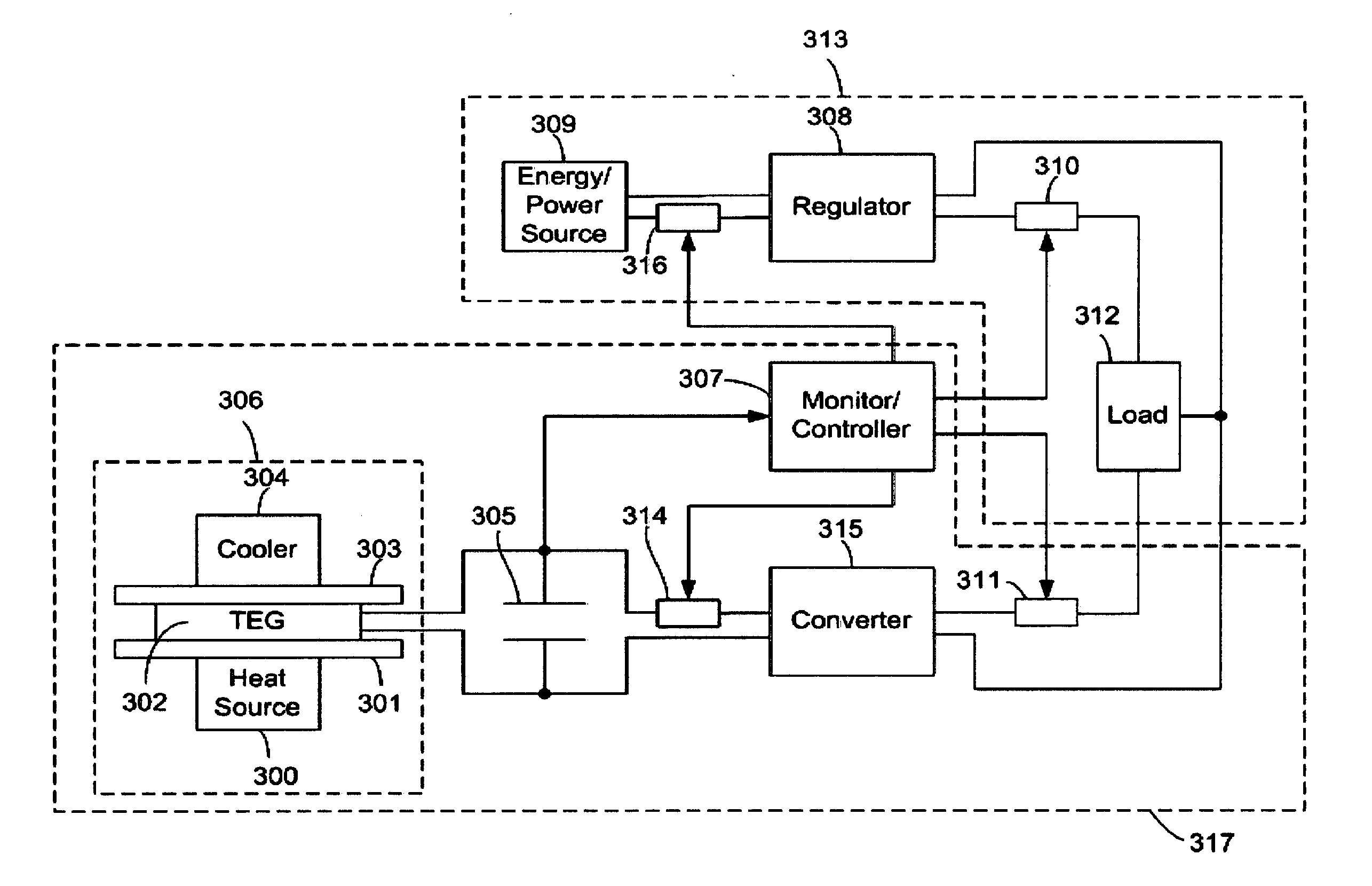
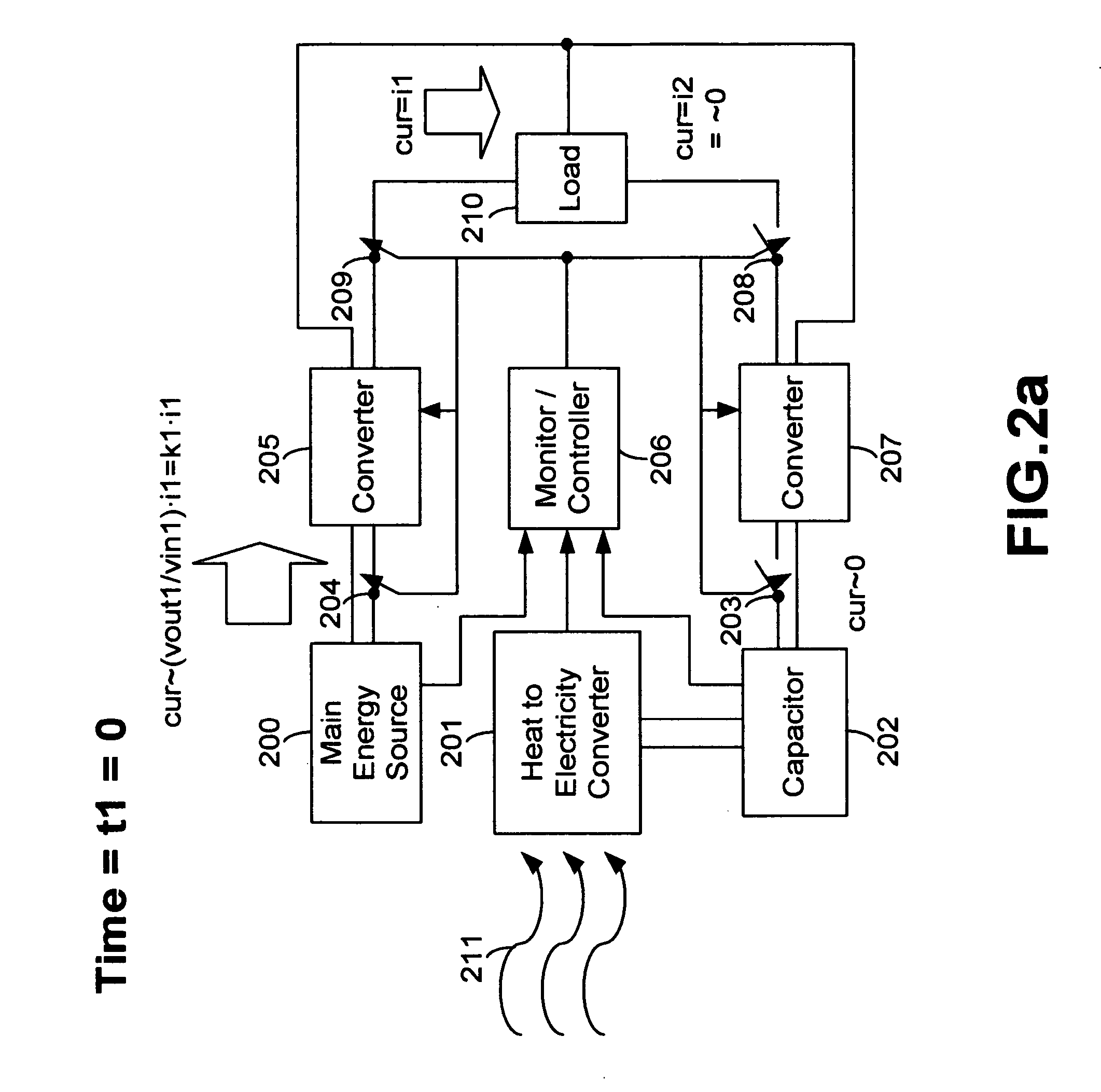
[0010] Described briefly in words, an electrical load is coupled to a main energy / power source and the object of the invention is to extend the life of this main energy / power source and reduce the amount of power drawn from the main energy / power source. Utilizing a second energy / power source whose energy is obtained by converting heat into electrical power (along with a capacitor, several switching elements, and a monitor / controller), energy / power drawn from the main energy / power source is reduced, thereby extending the operational life of the main energy / power source. In order to accomplish this objective, heat (which would be otherwise wasted) is converted into electrical energy or power by using a thermoelectric generator (TEG) and this electrical energy or power is then stored in a capacitor. The converted and stored energy or power is then used to supply power directly to an electrical load, thereby reducing power drawn from the main energy / power source. In a preferred embodiment, the heat can be produced by the main energy / power source, the electrical load itself, or any other internal or external (to the circuit or system in which the present invention is utilized) element that can produce heat.

Problems solved by technology

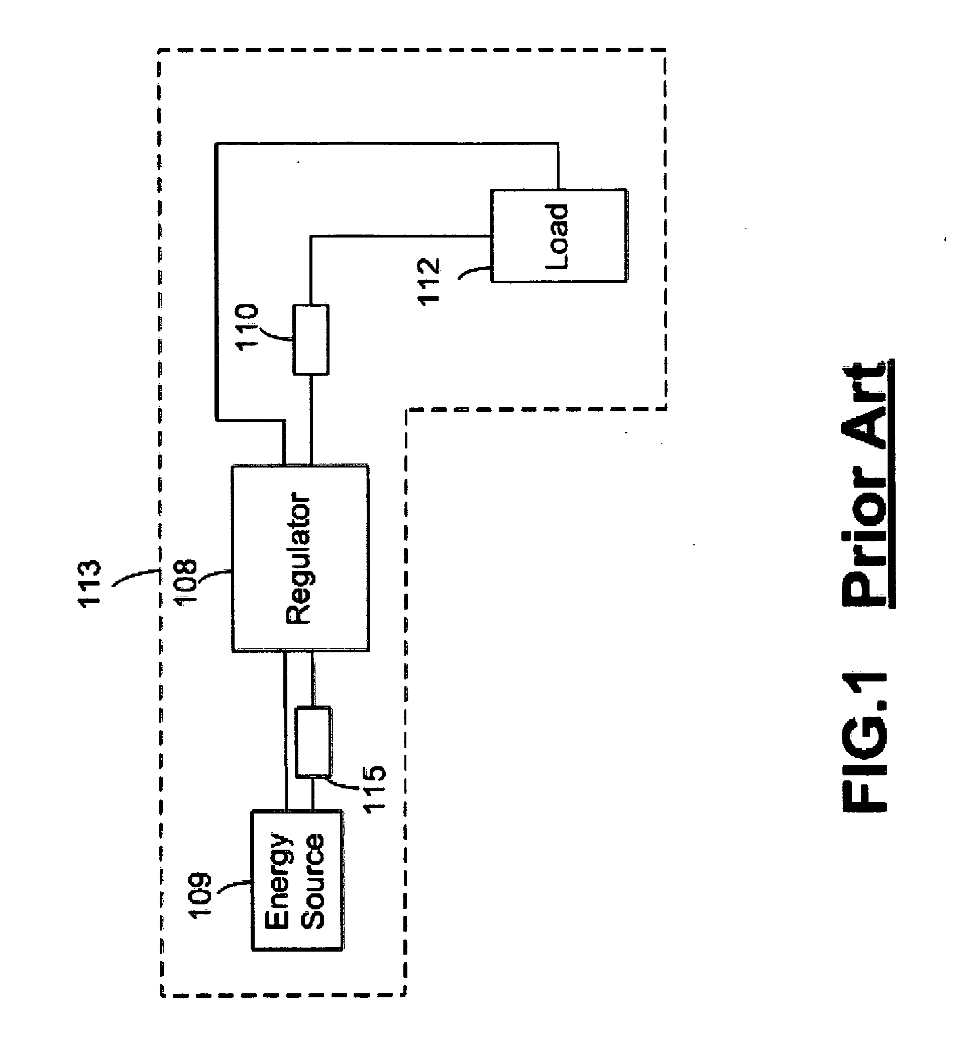
One problem with this system is that as the load increases in complexity and functionality, the amount of power required for driving the load increases.
While conventional power / energy supplies, such as disposable and / or rechargeable batteries are always improving in order to extend the length of the battery life, recent advances in high capacity batteries has not resulted in considerably longer battery life because the increase in power consumption of these electronic systems and devices more than offsets the improvement in battery life.
There are several disadvantages to the solution proposed by the Estes Patent.
First, the Estes Patent uses the electrical energy to directly recharge a main energy / power source—the rechargeable battery—such as a lithium-ion battery—which can only be accomplished through carefully controlling a complex electrochemical process.
Thus, the Estes Patent requires that the main power source be a rechargeable battery and further requires complex battery charging, conditioning and maintenance system circuitry, which must be built into the system.
Second, using the electrical energy to recharge the main power source can be inefficient in situations where the system is in use and the main power source must continue to provide energy / power to the load.
Accordingly, recharging of the battery would likely occur optimally at a time when the system is not in use and is not taxing or drawing charge from the battery; however, at such time the electrical device(s) in the system is not likely to generate much heat.
Therefore, the Estes Patent does not make optimal use of the heat generated by the system when it is active.
Finally, rechargeable batteries lose their charging / storage efficiency over time as they are repeatedly charged-discharged and / or continually used.
Accordingly, in the solution proposed by the Estes Patent, the efficiency and longevity of the life of the main power source—the rechargeable battery—may actually be decreased and system may become less efficient if the system is continually attempting to recharge the battery whenever it is turned on.

Method used


Image

  • System and method for efficient power utilization and extension of battery life
  • System and method for efficient power utilization and extension of battery life
  • System and method for efficient power utilization and extension of battery life

Examples


Embodiment Construction

[0017] The present invention improves power efficiency and can extend the operating life of a main energy / power source, such as a disposable battery, a rechargeable battery, a fuel cell, a power generator, a reactor, and / or any combination of these, i.e., hybrid power source(s), used to provide power to an electrical system or application. The main energy / power source can be either internal or external to the electrical system and may also be any form of power supply, such as power from an electrical outlet connected to a power grid.

[0018] In a preferred embodiment of the present invention the power efficiency of electrical systems is improved by reducing the power drawn from the main energy / power source as described in the following sections. It is also possible to supply extra power to an electrical load(s) with the embodiments of the claimed subject matter described herein.

[0019] Furthermore, it is possible to increase the operational life (“battery life”) and the power efficie...


PUM


Abstract

A circuit which extends the operational life of a main energy source coupled to a load, said circuit comprising a power generator having a heat source and a cooler thermally coupled to a thermoelectric generator (TEG) for converting thermal energy into electrical energy; and a first capacitor coupled to the TEG for receiving and storing the electrical energy from the TEG. The circuit further comprising at least one switching element coupled between the first capacitor and the load, a converter coupled between the capacitor and the at least one switching element for generating a regulated output, and a controller for activating the at least one switching element when the charge stored on the first capacitor reaches a predetermined level, thereby delivering power from the first capacitor to the load, via the converter, and reducing the amount of power drawn from the main energy source, thereby extending the operational life of the main energy source.

Description

FIELD OF THE INVENTION [0001] The invention generally relates to power systems and means for providing power to various electronic systems or devices. More particularly, the invention relates to an energy source, such as a battery, fuel cell, generator, and / or hybrid power supply, and a system and circuit for providing power to an electronic system or device which extends the operational life of the energy source, thereby allowing the energy source to provide power to the electronic system or device for an extended period of time. BACKGROUND OF THE INVENTION [0002] Electronic systems, devices and applications are continually developing. From cellular phones, portable computers, and compact fuel-cell based generators, to electrical vehicles, the list of electronic systems, devices and applications seems endless. As the number of systems and devices continues to increase, and the applications in which they are used continue to grow, the demand for efficient energy / power supplies that ...

Claims


Application Information

Patent Timeline
IPC IPC(8): H02J3/00
CPCH02J7/34H02J7/345
Inventor MAEDA, RYUJI
Owner MAEDA RYUJI
Learn More