Active damper with counter mass to compensate for structural vibrations of a lithographic system

a technology of lithographic system and counter mass, which is applied in the direction of shock absorbers, printing machines, instruments, etc., can solve the problems of inaccurate projection of images by the photolithography machine, improperly formed products formed using the precision instrument, and inability to function properly, so as to achieve relatively stable positioning of the optical central axis of the lens system

Inactive Publication Date: 2007-05-03
NIKON CORP
View PDF5 Cites 55 Cited by
  • Summary
  • Abstract
  • Description
  • Claims
  • Application Information

AI Technical Summary

Benefits of technology

[0009] An active damping arrangement which actively damps vibrations in a lens system of a photolithography apparatus is effective in creating a force to damp the vibrations responsive to the frequency of the vibrations. Typically, such an active damping arrangement includes an active mechanism and a counter mass. Since the active damping arrangement is adjustable, i.e., the force generated by the active damping arrangement may be varied, a wide range of vibrational frequen...

Problems solved by technology

When the performance of a precision instrument such a wafer scanning stage or a reticle scanning stage is adversely affected, products formed using the precision instrument may be improperly formed and, hence, function improperly.
A photolithography machine which is subjected to vibrations may cause an image to be inaccurately projected by the photolithography machine, and, as a result, be incorrectly aligned on a projection surface such as a semiconductor wafer surface.
Many components of a photolithography machine typically have vibrations modes which are relatively lightly damped and difficult to suppress.
By way of example, a lens mount system, which includes a lens base and sensor mount, of a photolithography apparatus generally has vibrations modes which, if not damped, may compromise the quality of an image projected onto a wafer surface.
When a ...

Method used


Image

  • Active damper with counter mass to compensate for structural vibrations of a lithographic system
  • Active damper with counter mass to compensate for structural vibrations of a lithographic system
  • Active damper with counter mass to compensate for structural vibrations of a lithographic system

Examples


Embodiment Construction

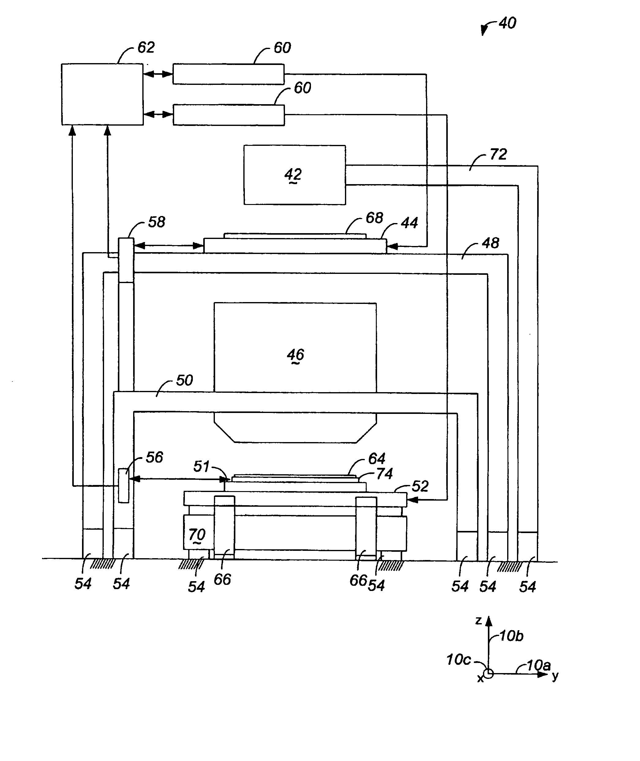
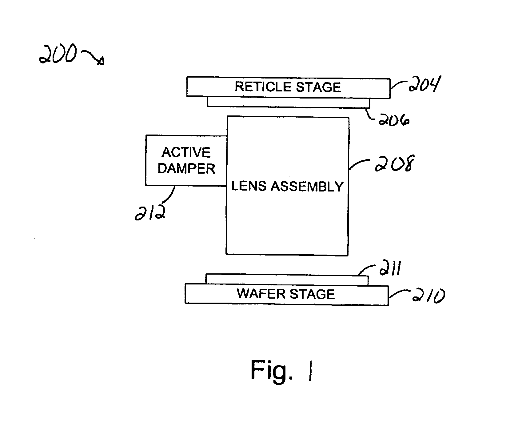
[0026] When an apparatus such a photolithography apparatus has components which vibrate, the accuracy of photolithographic processes performed using the apparatus may be compromised. For example, the stability of a lens base and a sensor mount of a lens system within a photolithographic apparatus is crucial, as an optical center of a lens is generally a reference position used to align a wafer and a reticle. In the event that the lens base and sensor mount vibrate or undergo structural oscillation, the reference position may move, and the alignment of the wafer and the reticle may need to be adjusted such that the wafer and the reticle remain aligned with the reference position. If the wafer and the reticle are not aligned with the reference position, the integrity of a photolithographic process which uses the wafer and the reticle may suffer.

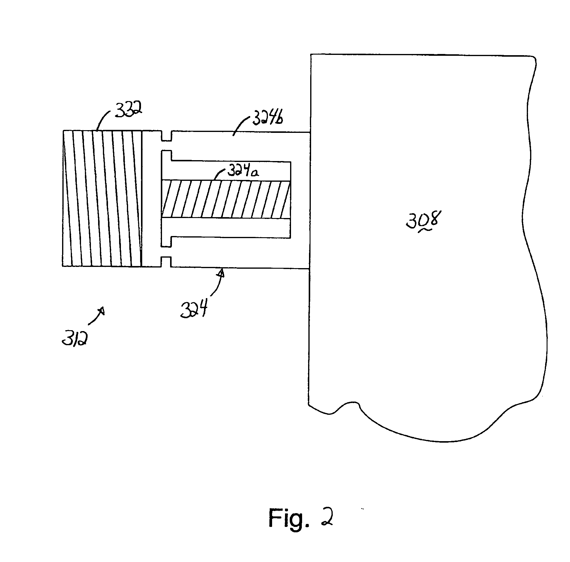
[0027] The utilization an active damper to damp vibrations of a lens system, e.g., a lens base and a sensor mount, allows structural oscillat...


PUM


Abstract

Methods and apparatus for actively damping vibrations associated with a optical assembly of a photolithographic system are disclosed. According to one aspect of the present invention, an assembly that provides damping to a structure of a photolithographic apparatus that is subject to structural oscillations includes a counter mass, an active mechanism, an a controller. The active mechanism is coupled to the structure, supports the counter mass, and applies a force to the structure to counteract structural oscillations in the structure. The controller controls the force applied by the active mechanism on the structure, and utilizes information associated with movement of the structure to control the force.

Description

BACKGROUND OF THE INVENTION [0001] 1. Field of Invention [0002] The present invention relates generally to damping vibrations associated with lithographic systems. More particularly, the present invention relates to an active damper with a counter mass which provides damping to a lithographic system. [0003] 2. Description of the Related Art [0004] For precision instruments such as photolithography machines which are used in semiconductor processing, factors which affect the performance, e.g., accuracy, of the precision instrument generally must be dealt with and, insofar as possible, eliminated. When the performance of a precision instrument such a wafer scanning stage or a reticle scanning stage is adversely affected, products formed using the precision instrument may be improperly formed and, hence, function improperly. [0005] A photolithography machine which is subjected to vibrations may cause an image to be inaccurately projected by the photolithography machine, and, as a resul...

Claims


Application Information

Patent Timeline
IPC IPC(8): G03B27/42
CPCF16F7/1005G03F7/70766G03F7/70833G03F7/709
Inventor YUAN, BAUSANCHANG, PING-WEIKAWAGUCHI, RYOICHIMASAKI, KAZUOMAKINOUCHI, SUSUMUTENG, TING-CHIEN
Owner NIKON CORP
Why Eureka
Try Eureka