Suppressed feature waveform for modulated sonar transmission

a sonar transmission and feature waveform technology, applied in the field of encoded sonar waveform production and use, can solve the problems of interference among the primary lobes of filtered pulses, lack of regular features, and inability to detect such encoded pulses,

Active Publication Date: 2007-05-03
DRS C3 & AVIATION
View PDF17 Cites 7 Cited by
  • Summary
  • Abstract
  • Description
  • Claims
  • Application Information

AI Technical Summary

Benefits of technology

[0010] In an embodiment, an advantage of a suppressed feature waveform sonar transmission as discussed herein is that the baseband waveform is essentially undetectable by a detector that is not provided with at least one of the pulse sequence waveform, the pulse sequence from which the pulse sequence waveform was generated, or the baseband waveform. Further alteration of the sonar transmission may include using at least one of the following techniques: power management, frequency diversification, directivity selection, or tactical techniques.

Problems solved by technology

For feature detectors not associated with the transmitter, however, detection of such an encoded pulse is difficult, if not impossible.
Where the frequency of the pulse sequence is sufficiently high as compared with the bandwidth of the bandpass filter, the increased pulse width resulting from the filtering causes interference among the primary lobes of the filtered pulses.
The result of the interference is a baseband waveform that generally lacks any regular features, and thus resembles noise.
Therefore, after modulation of the carrier wave with a baseband waveform so constructed, it is difficult to detect any features internal to the transmitted modulated carrier pulse, except through correlation with the pulse sequence.
Such interference may be generated when the pulse sequence waveform is passed through a bandpass filter.

Method used


Image

  • Suppressed feature waveform for modulated sonar transmission
  • Suppressed feature waveform for modulated sonar transmission
  • Suppressed feature waveform for modulated sonar transmission

Examples


Embodiment Construction

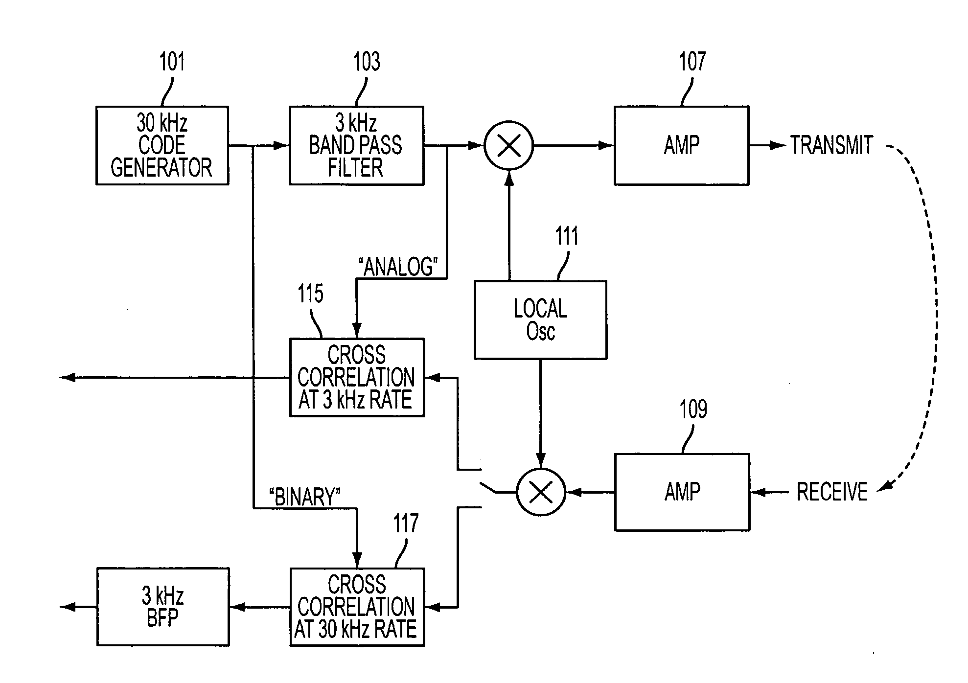
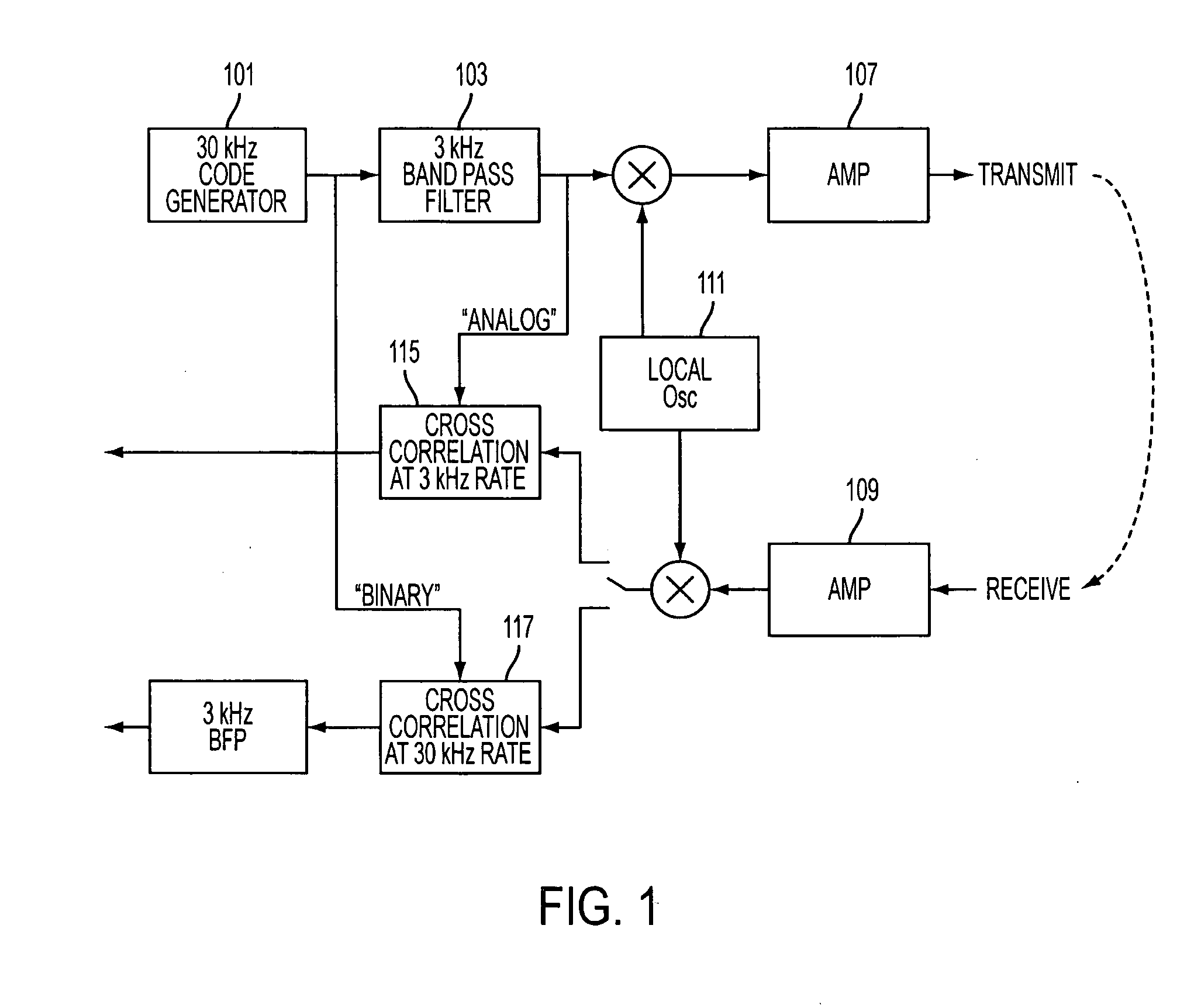
[0018] An embodiment as depicted in FIG. 1 generally operates as follows. A code generator 101 produces a pulse sequence at 800 kHz, preferably with the desired complementary properties. The pulse sequence is then passed through a bandpass filter 103 that limits the frequency bandwidth of the pulses to 80 kHz, thereby modifying the pulse sequence by changing the pulse shape and increasing the pulse width, particularly in the primary lobe. Because of the change in shape and width, the filtered pulses have significant interference among themselves, and no longer display any observable regularity. This irregular output from the bandpass filter 103 is a baseband signal that is then used to modulate a carrier wave generated by a local oscillator 111. The modulated carrier wave is then amplified in amplifier 107 before transmission from a transducer.

[0019] After reflection from an object some distance from the sonar transmission apparatus, a return signal pulse, received either by the tr...


PUM


Abstract

A suppressed feature waveform sonar transmission is produced by modulating a carrier wave with a baseband waveform that is generated from a known pulse sequence. A waveform embodiment of the pulse sequence is modified to create interference among the primary lobes of the constituent waveforms that are representative of the individual pulses. The baseband waveform so created appears as noise, making the baseband waveform modulation of the sonar transmission difficult to detect without knowledge of the pulse sequence or baseband waveform structure. The sonar transmission can be analyzed by cross-correlating the received signal with the baseband waveform or the pulse sequence waveform. The pulse sequence is preferably a complementary sequence. Modification of the pulse sequence may be obtained by passing an embodiment of the pulse sequence through a bandpass filter. In such a modification, the bandpass filter is preferably overdriven by a pulse sequence waveform having a frequency that is about eight to about ten times the bandwidth of the filter.

Description

CROSS REFERENCE TO RELATED APPLICATIONS [0001] This application claims priority to and claims the benefit of U.S. Provisional Patent Application 60 / 624,687, filed Nov. 3, 2004, which is wholly incorporated herein by reference.BACKGROUND OF THE INVENTION [0002] 1. Field of the Invention [0003] The invention generally provides a method and an assembly for the production and use of an encoded sonar waveform. More particularly, the invention provides a method and an apparatus that produces a modulated sonar pulse, wherein the baseband waveform modulating the pulse is encoded so as to resemble noise. [0004] 2. Description of Related Art [0005] Particularly in a time of war or anytime when a vessel is attempting to use sonar to collect information about an adversary, it is often desired that one's use of an active sonar system not be detected by the adversary. While there are methods of reducing the adversary's ability to detect the carrier wave of a traditionally modulated sonar pulse (s...

Claims


Application Information

Patent Timeline
Patent Type & Authority Applications(United States)
IPC IPC(8): H04K3/00
CPCG01S15/325H04B1/7075H04B2201/70715H04L25/03834
Inventor KREMER, LARRYZIEGLER, JOHNGOLDKAMP, DANIEL J.LINDQUIST, RICHARD
Owner DRS C3 & AVIATION
Why Eureka
Try Eureka