Parallel flow VHP decontamination system

a decontamination system and parallel flow technology, applied in the direction of disinfection, lavatory sanitory, chemistry apparatus and processes, etc., can solve the problem that the humidity level in a large room or isolator space to be sterilized cannot be easily controlled, and achieves the effect of reducing pressure drop, reducing waste, and reducing the size of blowers

Inactive Publication Date: 2007-05-03
AMERICAN STERILIZER CO
View PDF19 Cites 76 Cited by
  • Summary
  • Abstract
  • Description
  • Claims
  • Application Information

AI Technical Summary

Benefits of technology

[0007] An advantage of the present invention is a system for the sterilization or decontamination of a large room or isolated space.
[0008] Another advantage of the present invention is a system, as described above, that allows for varying the humidity level in the room or isolator during the operating cycle.
[0009] Another advantage of the present invention is a system, as described above, that reduces the pressure drop throughout the

Problems solved by technology

A problem with such systems is that the humidity level in a large room or isolator space

Method used


Image

  • Parallel flow VHP decontamination system
  • Parallel flow VHP decontamination system
  • Parallel flow VHP decontamination system

Examples


Embodiment Construction

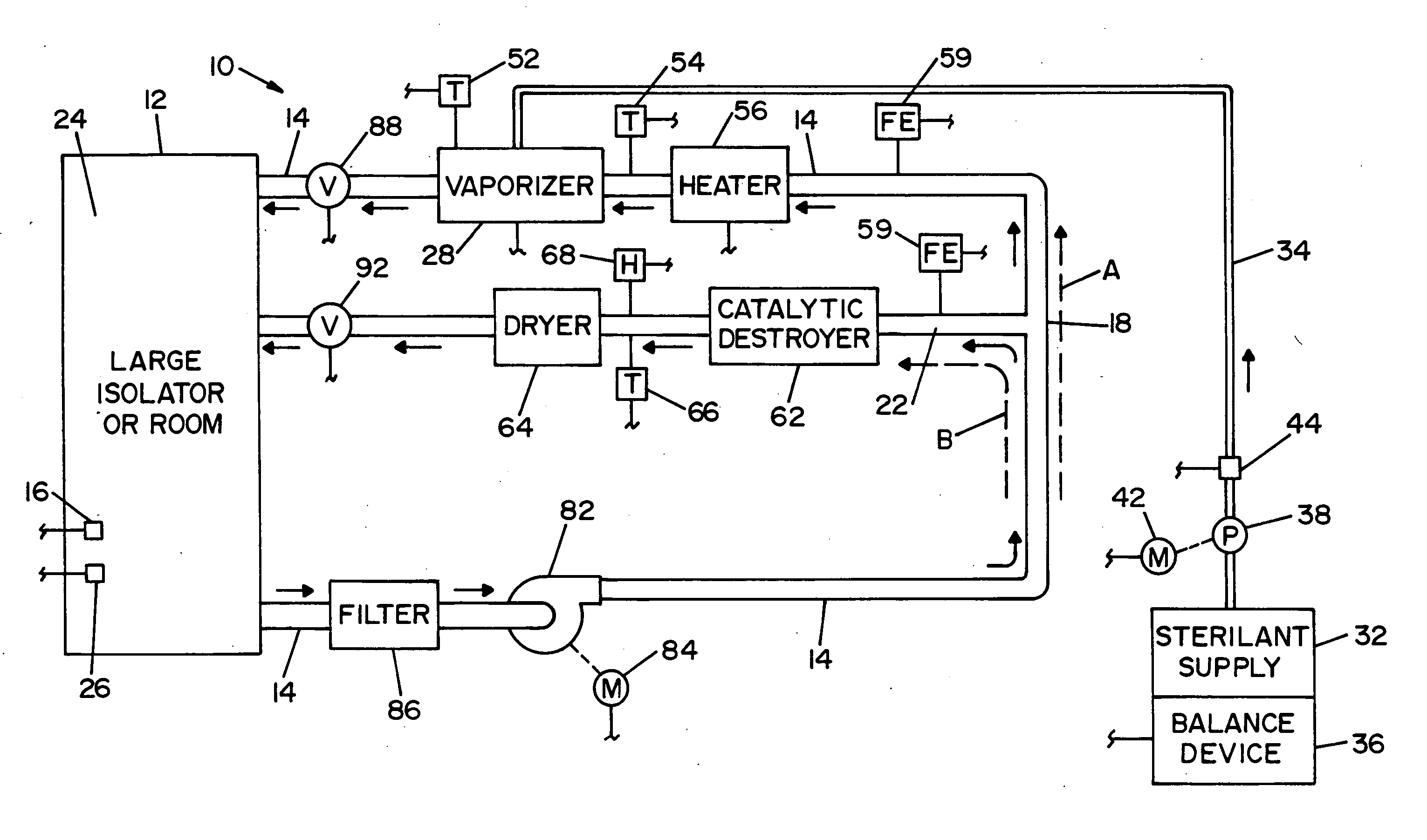
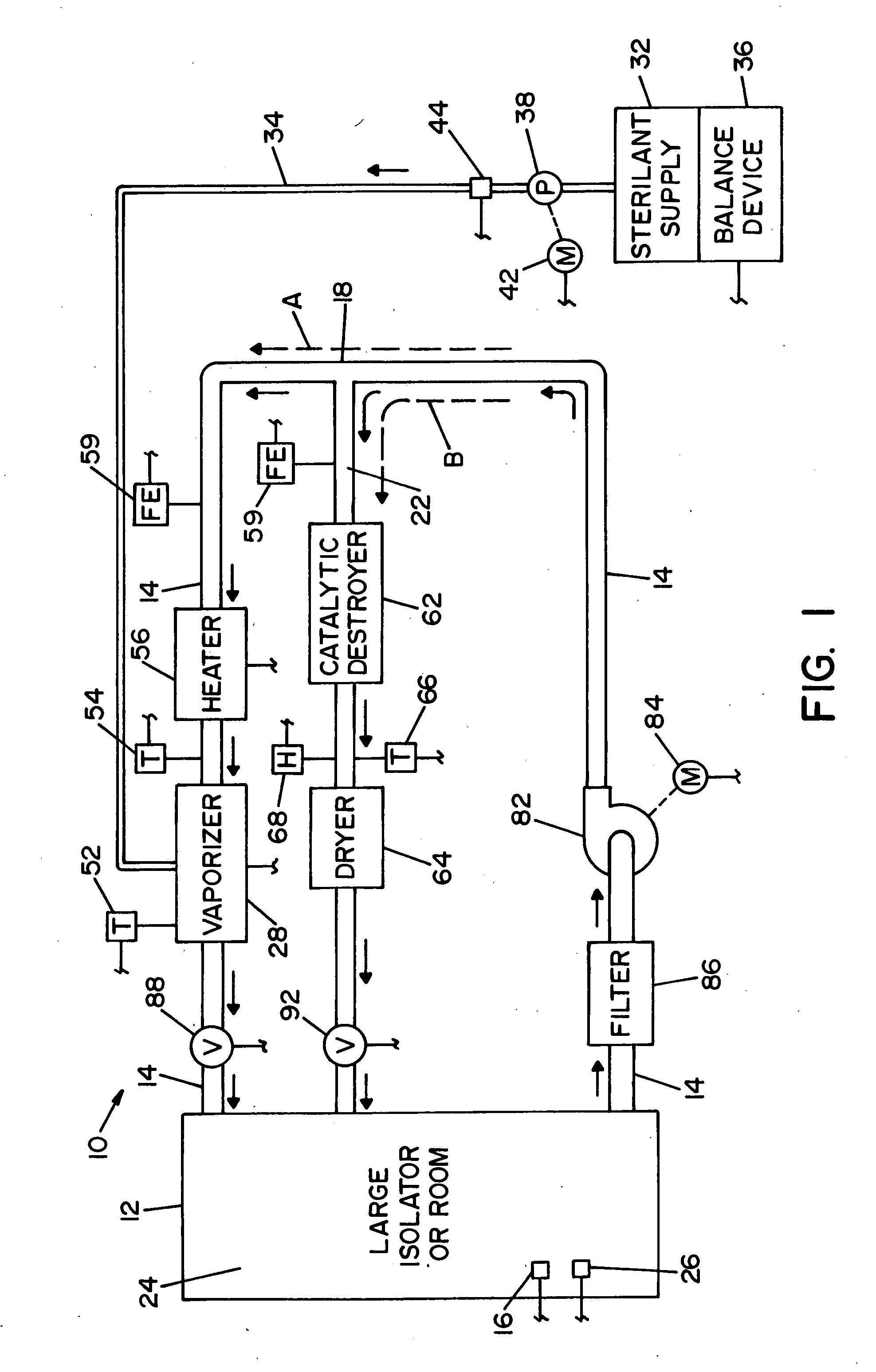
[0021] Referring now to the drawings wherein the showings are for the purpose of illustrating a preferred embodiment of the invention only, and not for the purpose of limiting same, FIG. 1 shows a vaporized hydrogen peroxide sterilization system 10, illustrating a preferred embodiment of the present invention. System 10 includes an isolator or room 12 that defines an inner sterilization / decontamination chamber or region 24. Articles to be sterilized or decontaminated may be disposed within isolator or room 12. A first humidity sensor 16 is disposed within isolator or room 12. First humidity sensor 16 is operable to provide a variable electrical signal that is proportional to the humidity of the carrier gas within isolator or room 12. A VHP sensor 26 is disposed within isolator or room 12. VHP sensor 26 can be an electrochemical cell that gives a signal proportional to the gas concentration or it can be a near infrared spectrophotometer that provides a similar signal or some other co...


PUM


Abstract

A closed loop vapor decontamination system for decontaminating a defined region. A chamber defines the region. A first fluid flow path connects at both ends to the chamber to define a closed loop path through the chamber. A second fluid flow path connects at both ends to the chamber to define a closed loop path through the chamber. The system has a means for conveying a carrier gas simultaneously along the first and second fluid flow paths. A generator generates vaporized hydrogen peroxide and is disposed along the first fluid flow path for introducing vaporized hydrogen peroxide into the carrier gas as it circulates through the first fluid flow path. A destroyer converts the vaporized hydrogen peroxide into water and oxygen and is disposed along the second fluid flow path for breaking down the vaporized hydrogen peroxide in the carrier gas as it circulates through the second fluid flow path. A controller operates to control the amount of the carrier gas flowing along the first and second fluid flow paths.

Description

FIELD OF THE INVENTION [0001] The present invention relates generally to the art of sterilization and decontamination, and more particularly to a system for controlling the humidity level in a sterilization or decontamination system that uses a sterilant in its gaseous or vapor phase. BACKGROUND OF THE INVENTION [0002] Gaseous and vapor sterilization / decontamination systems rely on maintaining certain process parameters in order to achieve a target sterility or decontamination assurance level. For Vaporized Hydrogen Peroxide (VHP) sterilization / decontamination systems, one such critical process parameter is the humidity level within the space where sterilization is to occur. By controlling the humidity level, it is possible to reduce the condensation of the hydrogen peroxide due to vapor saturation and thereby provide a more efficient sterilization / decontamination cycle. Conventional Vaporized Hydrogen Peroxide (VHP) sterilization systems for decontaminating large rooms or isolators...

Claims


Application Information

Patent Timeline
IPC IPC(8): A61L2/24A61L2/20
CPCA61L2/208A61L2/24A61L2202/14A61L2202/25
Inventor BUCZYNSKI, PETER J.ZELINA, FRANCIS J.HILL, AARON L.
Owner AMERICAN STERILIZER CO
Why Eureka
Try Eureka