
Enrobed core

a core and core technology, applied in the field of enrobed cores, can solve the problems of physical disintegration, affecting the quality of the product,

Inactive Publication Date: 2007-05-03
BUNICK FR J
View PDF4 Cites 11 Cited by
  • Summary
  • Abstract
  • Description
  • Claims
  • Application Information

AI Technical Summary

Benefits of technology

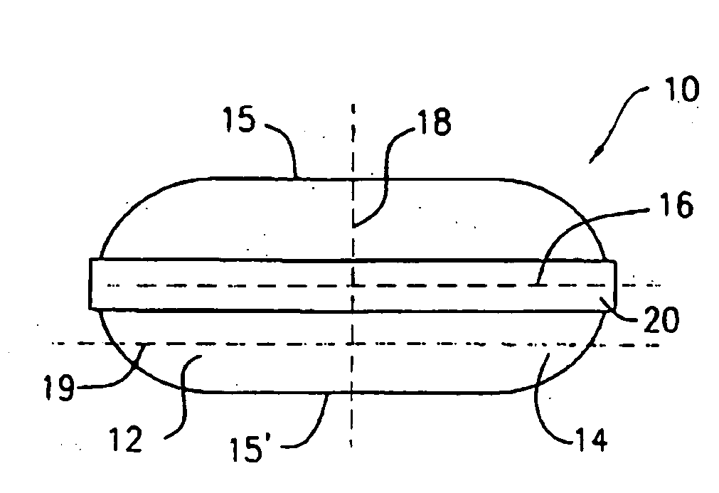
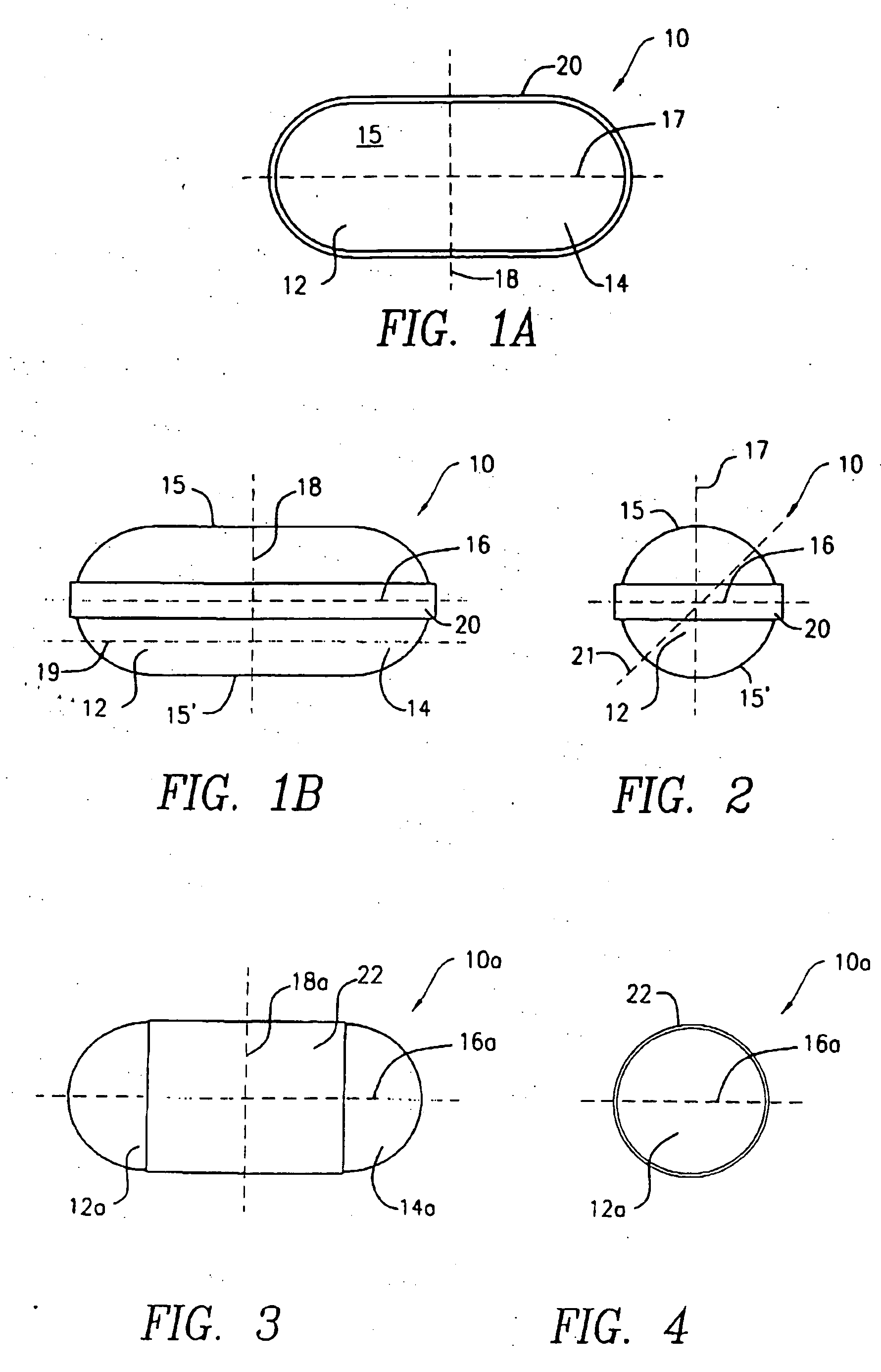
"The present invention is about a way to make a coated tablet that has a patterned film with different colored parts that meet in a continuous line on the surface of the tablet. This creates a unique and visually distinct appearance. The film can be made from two separate films that meet in a seam on the tablet. The resulting tablet can also be made with a bi-colored film that creates a checkerboard effect. The invention allows for a more visually appealing and distinctive tablet design."

Problems solved by technology

Tablets remain popular with consumers, however uncoated tablets suffer from drawbacks such as medicinal taste, a tendency to powder or flake (i.e., physical disintegration) when packaged in bottles, and / or the perception by consumers that they are not easy to swallow.
However, due to potential tampering concerns, capsules are no longer a preferred delivery choice for consumer (i.e., over-the-counter) pharmaceuticals.
However, such spray-coated tablets lack the glossy surface and elegance of the hard gelatin capsules.
Additionally, it is not commercially feasible to spray-coat a tablet with a different color coating on each end.
Each of the foregoing methods for producing tamper-proof coated tablets suffer from several shortcomings, including uneven color of the capsule halves and / or coatings, uneven thickness of the capsule halves and / or coatings, and the creation of raised seams between capsule halves and / or coatings.
Films prepared by this process suffer from the limitation of having multiple layers, with increased total film thickness in the area where the second film material is applied.
The increased film thickness creates an uneven appearance and feel to the surface, and retards dissolution, which is undesirable for immediate release dosage forms.

Method used


Image

  • Enrobed core
  • Enrobed core
  • Enrobed core

Examples


first embodiment

[0104] the present invention is directed to a novel rotary die apparatus and a method of enrobing cores using same. Initially, it is noted that, while various types of stock film forming materials are suitable for use in the embodiments described herein, gelatin-based materials are preferred.

[0105] U.S. Pat. Nos. 5,146,730 and 5,459,983 provide a complete and detailed description of the rotary die apparatus and method of enrobing cores to produce gelcaps suitable for use in the apparatus and method of the first embodiment. Accordingly, only those portions of the rotary die enrobing apparatus and process that are new and / or modified in accordance with the present invention will be described in full detail hereinafter.

[0106] Referring now to FIGS. 9-11, there are shown front (see FIG. 9), top (see FIG. 10) and side (see FIG. 11) representations of a film casting apparatus 30 used to produce a patterned film, more particularly a striped film 32, for enrobing cores 10 in accordance wit...

second embodiment

[0129] As illustrated in FIGS. 17-21, the present invention is directed to an alternative method for producing striped film having transversely oriented stripes, using rotary die apparatus and process that are nearly identical to those described above.

[0130] With reference particularly, to FIGS. 17-19, a simplified, schematic representation is provided of an alternative film casting apparatus 136, which produces the aforesaid transversely striped film 138 for enrobing cores 10 in accordance with the second embodiment of the present invention. More particularly, FIG. 17 shows an elevated side view of the alternative film casting apparatus 136, while FIG. 18 shows a top plan view thereof. FIG. 19 shows an elevated front view of the alternative film casting apparatus 136, as viewed from the position of line G-G in FIG. 18 and looking in the direction of the arrows.

[0131] Referring now to FIG. 17, the alternative film casting apparatus 136 includes film receiving means, such as a conve...

third embodiment

[0150] With reference initially to FIGS. 22, 23 and 26-30, the alternative enrobing apparatus in accordance with the present invention includes a conveyor system 220 (see FIG. 22) that comprises a series of horizontally-oriented rollers 222 and pairs of rollers, 224, 226, 228 (see FIGS. 26-30), for supporting and conveying the transversely striped film 138. The conveyor system 220 will be described in greater detail hereinafter in connection with FIG. 26.

[0151] It will be recalled that the film 138 has alternate transversely-oriented red stripes 172, 176 and yellow stripes 174, 178 with color transitions 186, 188, 190 therebetween (see, e.g., FIGS. 18 and 20), although, as set forth above, any stock film forming materials having other colors or other visual distinctions or appearances are suitable. A core dispensing means 230 is positioned above the conveyor system 220 and the film 138 for the purpose of dispensing the cores 10 onto the film 138 in the required orientation with resp...


PUM

PropertyMeasurementUnit
temperatureaaaaaaaaaa

Abstract

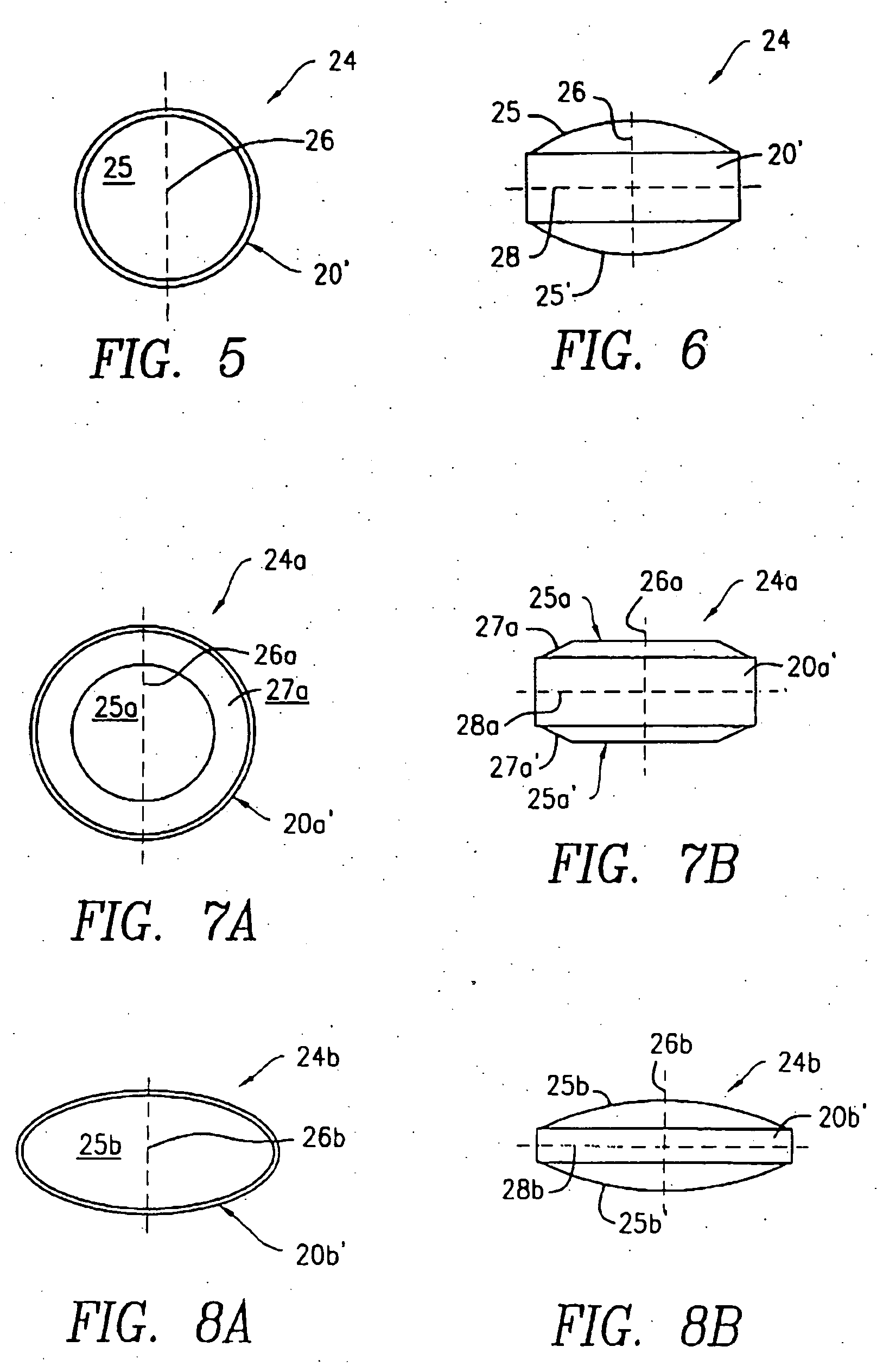
An enrobed a core, such as a tablet core, that has a coating made of one or more patterned films each having portions that are visually distinct (e.g., differently colored) from one another and having a transition line segment between these visually distinct portions. At least a portion of an outer surface of the core is covered with the film or films, such that the transition line segments form a substantially continuous transition line on the coating and a film seam is formed which is different from the transition line. Where the patterned films are bi-colored, the resulting enrobed core can be bi-colored, or the resulting enrobed core can have a coating with at least four visually distinct portions alternately arranged thereon, thereby forming a “checkerboard” pattern on the coating. In either case, the film seam of the coating is different from the transition line of the coating.

Description

FIELD OF THE INVENTION [0001] The present invention relates to an enrobed core, such as a tablet core, having a patterned coating formed by one or more patterned films. BACKGROUND OF THE INVENTION [0002] Various oral dosage forms have been developed over the years for pharmaceuticals and dietary supplements. Among the more popular oral dosage forms are tablets, capsules and, most recently, gelcaps. Tablets are compressed or molded solid dosage forms of any size or shape. Solid, generally oblong-shaped tablets may sometimes be referred to as caplets. Tablets remain popular with consumers, however uncoated tablets suffer from drawbacks such as medicinal taste, a tendency to powder or flake (i.e., physical disintegration) when packaged in bottles, and / or the perception by consumers that they are not easy to swallow. These limitations are eliminated by coating the tablets with a polymeric coating. [0003] During most of the 20th century, hard gelatin capsules were a popular dosage form f...

Claims


Application Information

Patent Timeline
Patent Type & Authority Applications(United States)
IPC IPC(8): B31B45/00A61K9/20A61K9/28A61K9/48
CPCA61K9/2072A61K9/209A61K9/2893A61J3/005Y10T428/1352B30B11/34Y10T428/2935Y10T428/13Y10T428/2933B30B11/16A61K9/00
Inventor BUNICK, FRANK J.
Owner BUNICK FR J
Learn More