Customizable chip and method of manufacturing the same

a chip and customization technology, applied in the field of chips, can solve the problems of not being able to meet two or more different combinations of tests on the same chip, the number of tests achievable on a single chip would be limited by the size of the chip, and the analysis system could never be put into practice, so as to enhance the utility of the chip, customize the configuration of the chip, and improve the effect of standardization

Inactive Publication Date: 2007-05-03
NEC CORP
View PDF1 Cites 59 Cited by
  • Summary
  • Abstract
  • Description
  • Claims
  • Application Information

AI Technical Summary

Benefits of technology

[0010] It is possible to customize the configuration of a chip by setting an opening or a closing the flow control portions, thereby obtaining chips for the different test items. Thus, it is possible to readily obtain a chip whose channel configuration is most suitable for achieving the test required for a given patient or for determining the required clinical parameters. Since the chip includes flow control portions, it makes it unnecessary to prepare in advance a huge number of chips with different lay-outs corresponding to s huge number of test parameters. Because of the above-cited advantages, it is possible according to the invention to stably produce general-purpose chips receptive to customization at a low cost. Moreover, it is possible according to the invention to distribute a sample only to necessary channels by providing the flow control portion, which will allow the efficient use of the sample. Therefore, even if the amount of a sample is very small, it will be possible to reliably perform necessary tests on that sample. It is also possible to minimize the consumption of reagents required for analysis.
[0067] The chip of the invention may be so constructed as to have the same number of general-purpose analysis portions with that for a sample, and may be subjected to the same analysis task using a standard solution instead of the sample. The result obtained by the chip from the standard solution may be compared with the result obtained by the test chip using a sample. The comparison will further enhance the accuracy of the diagnosis by the test chip.

Problems solved by technology

If micro total analysis systems were applied to the clinical laboratory test and the like, the number of tests achievable on a single chip would be limited by the size of the chip.
Thus, such analysis system, could never been put into practice.
In addition, a chip having one definite layout cannot meet two or more different combinations of tests.

Method used


Image

  • Customizable chip and method of manufacturing the same
  • Customizable chip and method of manufacturing the same
  • Customizable chip and method of manufacturing the same

Examples


first embodiment

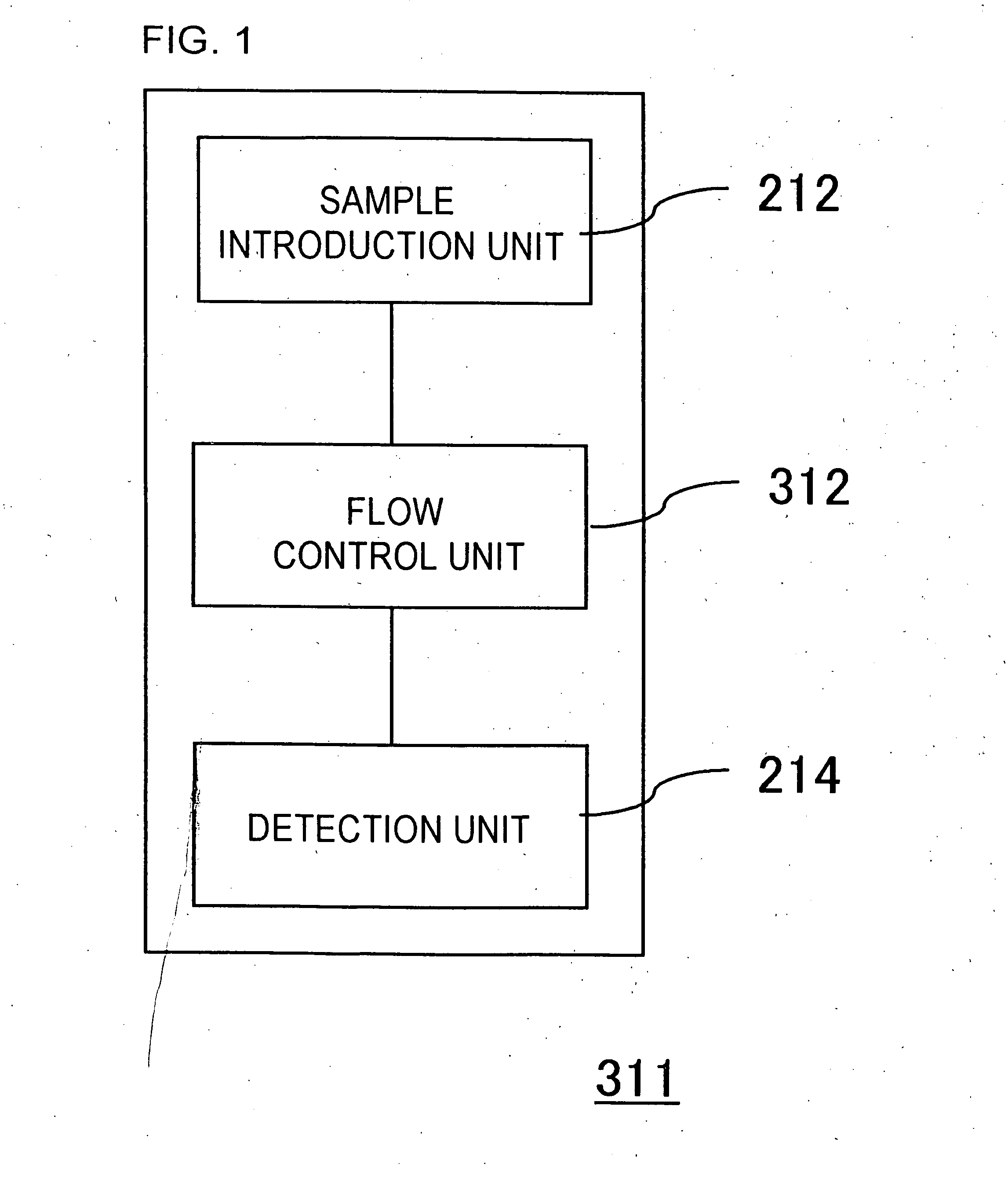
[0130] This embodiment represents a chip that enables the determination of some parameters selected from available plural test items. The chip includes plural detection units responsible for the determination of respective test items, which will also serve as analysis portions. Each detection unit is in communication with a dispensing channel to which is provided a flow control unit which determines whether downward flow of liquid through the dispensing channel should be permitted or not. The chip is configured such that a sample is guided only to the detection units responsible for the determination of test items required for a given test, by setting an opening and closing of the flow control units connected to relevant detection units.

[0131]FIG. 1 shows a block diagram for representing the functional components of a chip representing the first embodiment. The chip shown in the FIG. 1 allows one to analyze the elements of a sample, and includes a sample introduction unit 212, a fl...

second embodiment

[0176] This embodiment represents a chip that enables the selection of some parameters out of available plural parameters for the measurement by external measuring apparatuses. The chip includes plural measurement units responsible for the determination of respective detection parameters, which will also serve as analysis units. Each measurement unit is in communication with a dispensing channel to which is provided a flow control unit for adjusting the downward flow of liquid through the dispensing channel. The chip is configured such that a sample is guided only to the measurement unit responsible for the necessary parameters, by setting an opening and a closing of the flow control units connected to relevant measurement units.

[0177]FIG. 10 is a block diagram for representing the functional components of a chip representing this embodiment. A chip 315 is different from the one represented by the first embodiment in that it includes a measurement unit 233 instead of the detection ...

third embodiment

[0196] The chip described in relation to the first and second embodiments may further include a separation unit for separating specified components of a sample before the sample is subjected to analysis (detection or measurement), at an intermediate stage between the sample sample introduction unit 212 and the flow control unit 312. FIGS. 19 and 20 are block diagrams for representing the functional components of chips representing this embodiment of the invention. The chips 324 and 325 shown in FIGS. 19 and 20 respectively further include a separation unit 213 between sample introduction unit 212 and flow control unit 312 and makes it possible to perform analysis (detection or measurement) on the component separated in advance from a sample. Description will be given below taking as an example a chip including a detection unit 214, which serves as an analysis unit (FIG. 19).

[0197]FIG. 21 is a diagram for representing the components of an exemplary chip further including a separatio...


PUM


Abstract

The present invention provides an analysis chip allowing customization in accordance with the items required for a given test, and method for producing the same. On a chip (313) there are formed dispensing channels (222) connected to respective detection reservoirs (223) and branching off from a main channel (221). Each branch channel (222) is provided with a flow control unit (314) responsible for an opening and closing of the channel. It is possible to achieve multiple analysis steps by appropriately setting an opening and closing of flow control units provided to an analysis portion.

Description

TECHNICAL FIELD [0001] The present invention relates to a chip allowing customization of its configuration and the method of producing it. BACKGROUND ART [0002] Recently, use of micro total analysis systems (μ-TAS) in which chemical operation such as the pretreatment of a sample, and its reaction, separation and detection is performed on a microchip has rapidly advanced. Such micro total analysis systems allows the use of a small amount of sample, imposes less burden to the environment, and enables high sensitivity analysis. Thus, if it were possible to apply such microchip based analysis to the clinical laboratory test in medicine, it would be highly advantageous because then the laboratory test could be easily performed on tiny amounts of samples. Non-patent Document 1: David, S. J., Dwight, K. O., and Wayne, R. D. (Eds.), 2001, “Laboratory Test Handbook with Key Word Index,” 5th edition, Lexi-Comp Inc., Hudson, Ohio, pp. 77-80 DISCLOSURE OF THE INVENTION [0003] If micro total an...

Claims


Application Information

Patent Timeline
Patent Type & Authority Applications(United States)
IPC IPC(8): C12M1/34B01L3/00
CPCB01L3/502707B01L3/502738B01L3/502746B01L3/502753B01L2200/10B01L2300/0654B01L2300/0681B01L2300/0816B01L2300/0864
Inventor IIDA, KAZUHIROTANAKA, TAKASHI
Owner NEC CORP
Why Eureka
Try Eureka