Device for reaction or separation and a continuous esterification process using the device

Active Publication Date: 2007-05-03
CHINA PETROCHEMICAL CORP +2
View PDF3 Cites 7 Cited by
  • Summary
  • Abstract
  • Description
  • Claims
  • Application Information

AI Technical Summary

Benefits of technology

[0017] Not to be limited by any theory, the inventor considers that in the device of the present invention, the container is a double-chamber structure and the inner chamber and the outer chamber connect with a U-shape pipe, which serves as a passage of the liquid materials. Therefore, the materials present in the U-shape pipe form a liquid seal while working, which, in combination with the throttling function of the throttling controller in the connecting pipe, lays the inner chamber and outer chamber in a relative isolation state. In general, the pressure of the space above the liquid level of the outer chamber or inner chamber mainly depends on the volume of the space and the amount of the vapor materials escaped due to evaporation or reaction, wherein the pressure is inversely proportional to the volume of the space, and directly proportional to the amount of the escaped vapor materials. When the factors in the device such as the materials, temperature, reaction nature, etc. are determined, the amount of the escaped vapor is knowable. As said previously, the top of the inner chamber may locate below ½ of the height of the continuous space fr

Problems solved by technology

The drawbacks of the continuous stir reactor are evident, i.e., the occurrence of the temperature field and concentration field of the internal materials caused by the amplification of the device, which affect the uniformity of the materials, a high investment resulted from large numbers of the devices and powerful stirring equipments, and a considerable operation cost of the stirring equipments.
However, such a prior externally circular heating esterification device has an evident drawback.
The driving force for the stream only comes from the thermal siphon, but the flow rate is generally difficult to meet the requirement of the process only using t

Method used


Image

  • Device for reaction or separation and a continuous esterification process using the device
  • Device for reaction or separation and a continuous esterification process using the device
  • Device for reaction or separation and a continuous esterification process using the device

Examples


Example

EXAMPLE

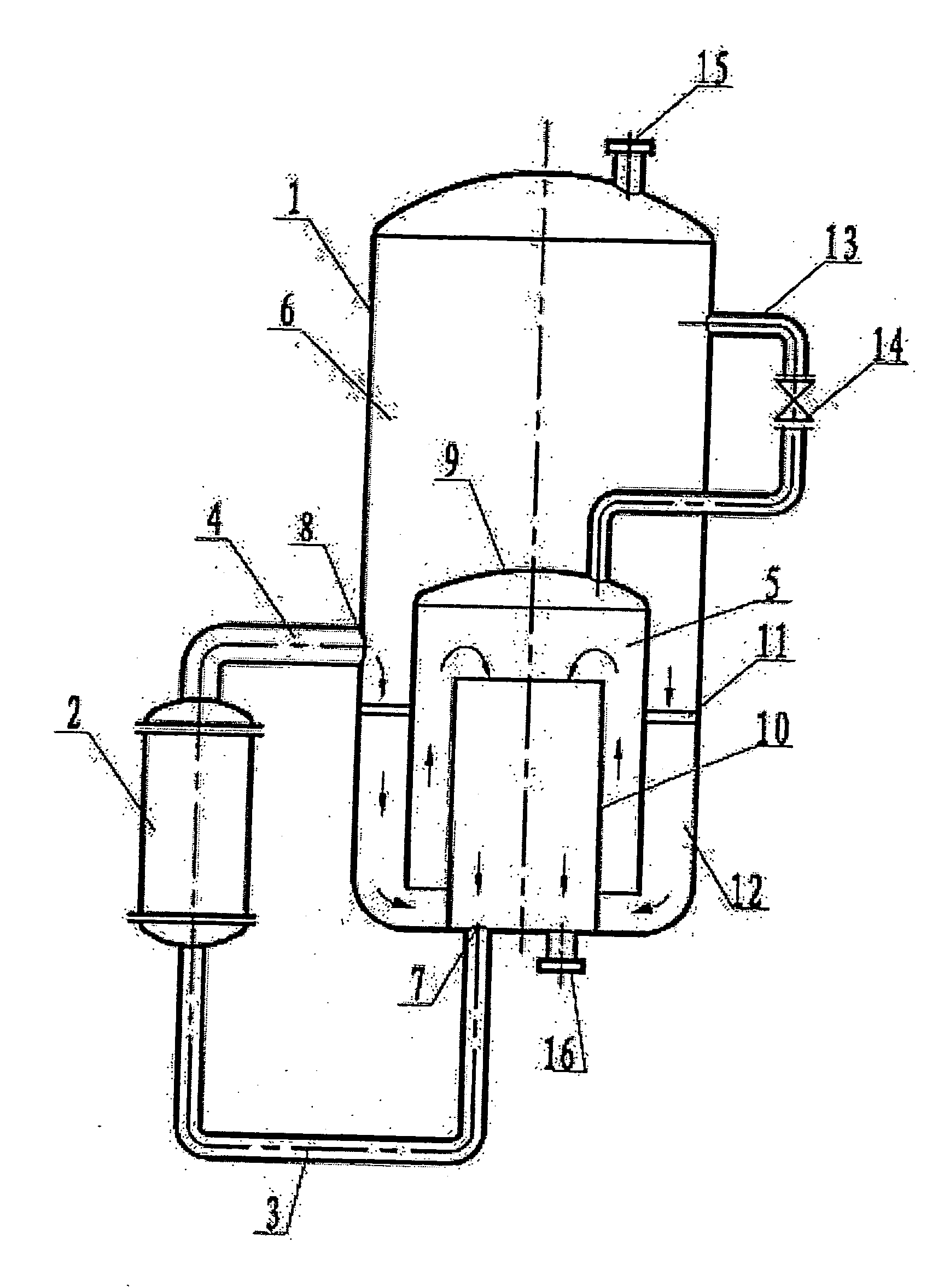
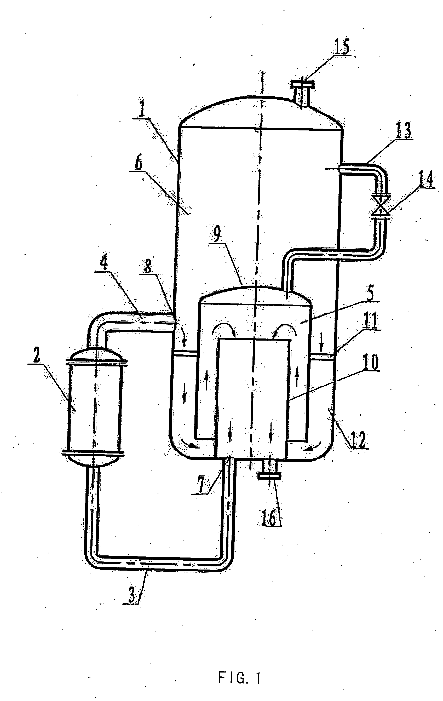
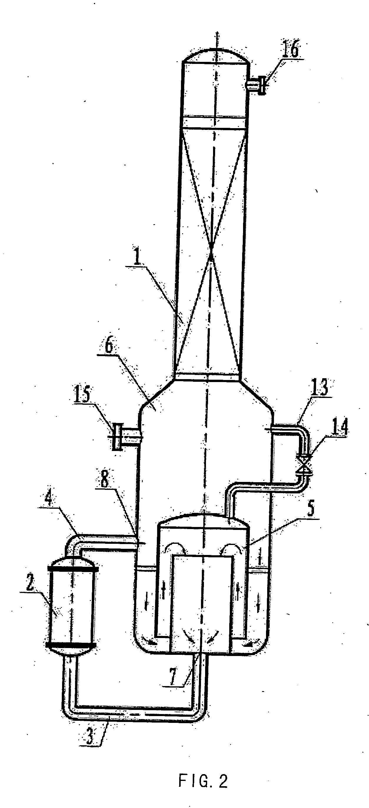
[0028] The esterification reactor was composed of an esterification heater heated with a hot vapor medium and a reaction kettle connecting in series with a U-shape pipe, wherein the heater was a tube heat exchanger and the reaction kettle was a jacketed cylinder structure. A slurry feed consisting of PTA and EG entered the system through a feed nozzle, mixed with the liquid circular materials from the inner chamber of the reaction kettle, and then entered the external circular shell and tube heat exchanger for heating. The molar ratio of EG to PTA was controlled at 1.8:1. The materials were heated to 282° C. by passing through the heater and converted to water and other by-products (e.g. diglycol, etc). In the reaction kettle, there was enough vapor space above the liquid level to prevent the entrainment. The vapor-liquid mixture sprayed from the heater was subjected to flash separation to remove water and the vapor of ethylene glycol, and entered the separation tower throug...


PUM

PropertyMeasurementUnit
Temperatureaaaaaaaaaa
Pressureaaaaaaaaaa
Pressureaaaaaaaaaa

Abstract

The present invention relates to a reaction or separation device, wherein the materials circularly flow in a container and a pipe. Said device contains a container and an external circular pipe, wherein the container is a double-chamber structure. The inner chamber consists of an outer cylinder and an inner cylinder with the latter being jacketed by the former, and there is a space between the walls of the outer cylinder and the inner cylinder. The lower end of the outer cylinder is open and higher than the bottom of the container, and the outer cylinder is fixed to the wall or bottom of the container. The upper end of the inner cylinder is open and its lower end connects with the external circular pipe through the feed outlet. A continuous passage is sequentially formed from the spaces between the wall of the outer cylinder and that of the container, between the lower end of the outer cylinder and the bottom of the container, between the wall of the outer cylinder and that of the inner cylinder, and in the inner cylinder. The external circular pipe connects with the bottom of the container and leads to the inner chamber, and connects with the sidewall at the lower part of the container and leads to the outer chamber, respectively. The present invention also relates to a continuous esterification process, which comprises feeding liquid reaction materials to the reaction device and carrying out reaction under reaction conditions.

Description

TECHNICAL FIELD [0001] The present invention relates to a device for reaction or separation. In particular, it relates to a reaction or separation device wherein the materials circularly flow in a container and a pipe, and the use of said device as a continuous esterification device. The present invention also relates to a continuous esterification process using said device, which comprises feeding liquid reaction materials to said device and carrying out reaction under the esterification conditions. BACKGROUND ARTS [0002] In chemical production, there exist a large number of container devices for reaction or separation that use external circular heating, such as devices for producing polyesters, wherein the container may be a kettle or a tower. The raw materials to be heated generally enter an external heat exchanger from the bottom of the container through a pipe for heating, and then return to the container from the wall at the lower part of the container through the pipe. There ...

Claims


Application Information

Patent Timeline
IPC IPC(8): C08G63/00B01J19/00C07C69/76B01F5/06B01F5/10B01J8/38
CPCB01F5/0659B01F5/10B01J8/388B01F25/435B01F25/50
Inventor CHEN, ZHENXINYU, MINGKANGWANG, SHAOPENG
Owner CHINA PETROCHEMICAL CORP
Why Eureka
Try Eureka