Suture anchor cartridge holder, suture anchor cartridge and associated method

a cartridge holder and cartridge technology, applied in the field of orthopaedics, can solve the problems of stress on joints or damage to bones, wear and tear of cartilage, and damage to other connective tissues such as tendons or ligaments, and achieve the effect of quick loading or refilling of anchor cartridges, convenient positioning, and quick loading of cartridges into the applicator

Inactive Publication Date: 2007-05-03
DEPUY PROD INC
View PDF28 Cites 172 Cited by
  • Summary
  • Abstract
  • Description
  • Claims
  • Application Information

AI Technical Summary

Benefits of technology

[0029] The technical advantage of the present invention also includes the ability to securely place the anchors. For example, according to yet another aspect of the present invention, a suture anchor cartridge assembly is provided for performing surgery on tissues of a patient. The suture anchor cartridge assembly includes a body, a cartridge and an anchor. The body includes a surface closely conforming to the surface where the anchors are to be placed, as well as a inserting rod that may be positioned with a stop to accurately and securely place the anchor relative to the position in the body where it is to be placed. Thus, the present invention provides for securely placing the anchors in the body.
[0030] The technical advantages of the present invention also include the ability to quickly load or refill an anchor cartridge to repair subsequent surgeries. For example, according to yet another aspect of the present invention, a suture anchor cartridge assembly for use in performing surgery on a patient is provided. The cartridge assembly includes a body and a cartridge removably secured to the body. Anchors are operatively associated or positioned on the cartridge. The cartridge may be quickly removed from the body after the anchors have been separated from the cartridge. A second or new cartridge may be easily positioned onto the body, so that a subsequent use of the body may occur. Thus, the present invention provides for the ability to quickly load a cartridge into the applicator.
[0031] The technical advantages of the present invention also include the ability to sterilize the cartridge assembly. For example, according to another aspect of the present invention, the suture anchor cartridge assembly may include a body, a cartridge and an anchor, each of which may be sterilizable. The cartridge may be pre-loaded with the anchors with the cartridge and anchor pre-sterilized. The body may include components that are readily disassembled. The body may be resterilizable and be made of sterilizable components that are sterilizable from a commonly available sterilizing technique, such as by an autoclave. Thus, the present invention provides for a suture anchor cartridge assembly that may be sterilized.
[0032] The technical advantages of the present invention further include the ability to provide for a disposable cartridge. By providing a disposable cartridge that includes preassembled anchors, the cartridge when spent, may be disposed. Thus, the amount of effort or time by the surgery team may be minimized to merely inserting a new cartridge into a sterile cartridge holder or body. Thus, the present invention provides for a disposable cartridge.
[0033] Other technical advantages of the present invention will be readily apparent to one skilled in the art from the following FIGS., descriptions and claims.

Problems solved by technology

The joints in the body are stressed or can be damaged in a variety of ways.
Overtime, the normal use of a joint may wear down the cartilage and bring the moving bones in a direct contact with each other.
In contrast, in normal use, a trauma to a joint, such as the delivery of a large force, from an accident for, example, an automobile accident, may cause considerable damage to the bones, the cartilage or to other connective tissue such as tendons or ligaments.
Such erosion of the scapula renders treatment difficult, if not impossible, with a conventional glenoid prosthesis.
The securing of soft tissue and such extra cellular matrix sheets to the tissues is a slow and time-consuming process.
This problem is particularly apparent when implanting a glenoid-resurfacing patch.
This process is slow and time consuming.
Therefore, this slow and tedious process increases the length of time required for the patient in the surgery room.
Further, the surgeon may place the sutures in a pattern that may be less than the ideal pattern due to difficulty in accessing the glenoid fossa.

Method used


Image

  • Suture anchor cartridge holder, suture anchor cartridge and associated method
  • Suture anchor cartridge holder, suture anchor cartridge and associated method
  • Suture anchor cartridge holder, suture anchor cartridge and associated method

Examples


Embodiment Construction

[0071] Embodiments of the present invention and the advantages thereof are best understood by referring to the following descriptions and drawings, wherein like numerals are used for like and corresponding parts of the drawings.

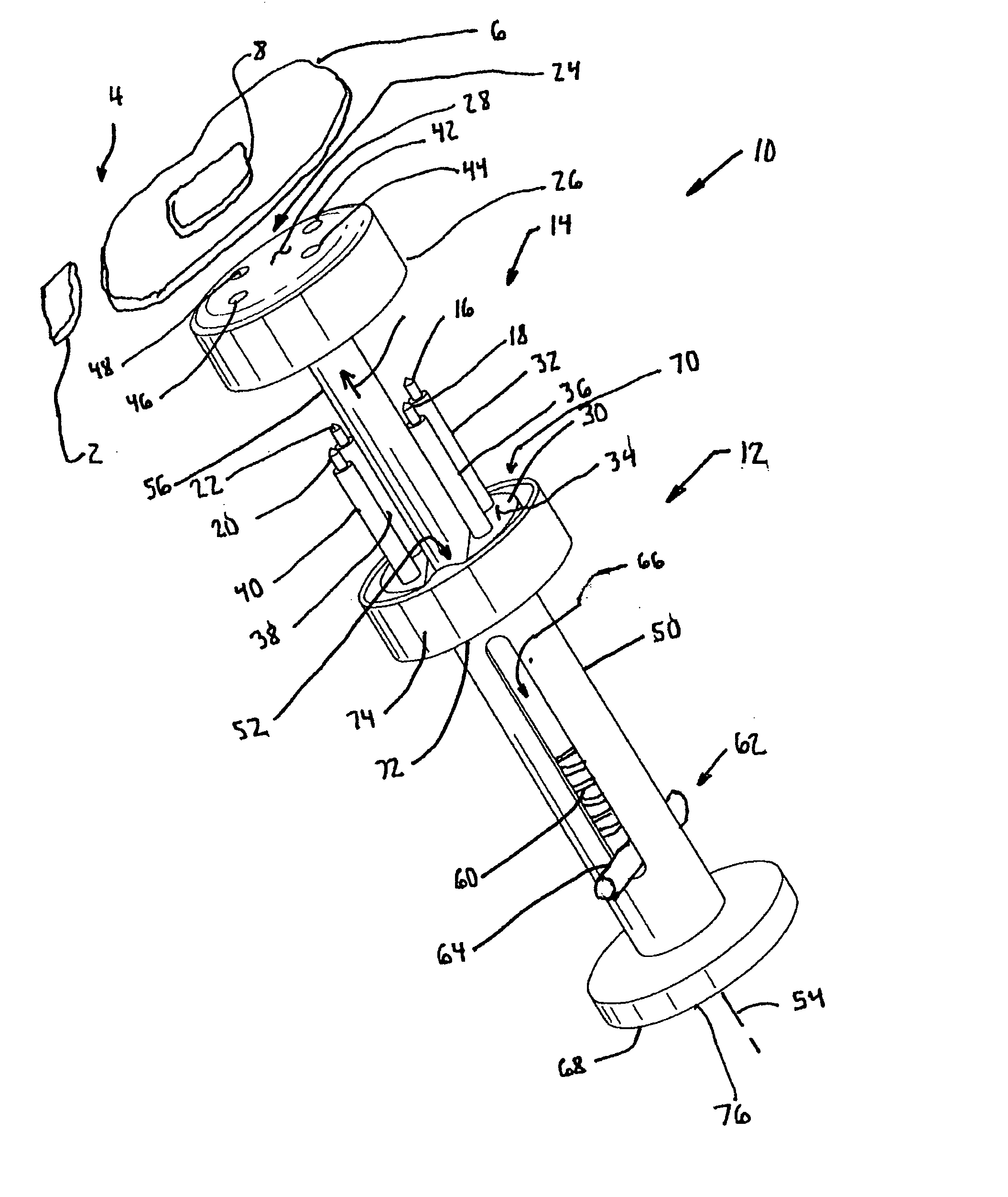
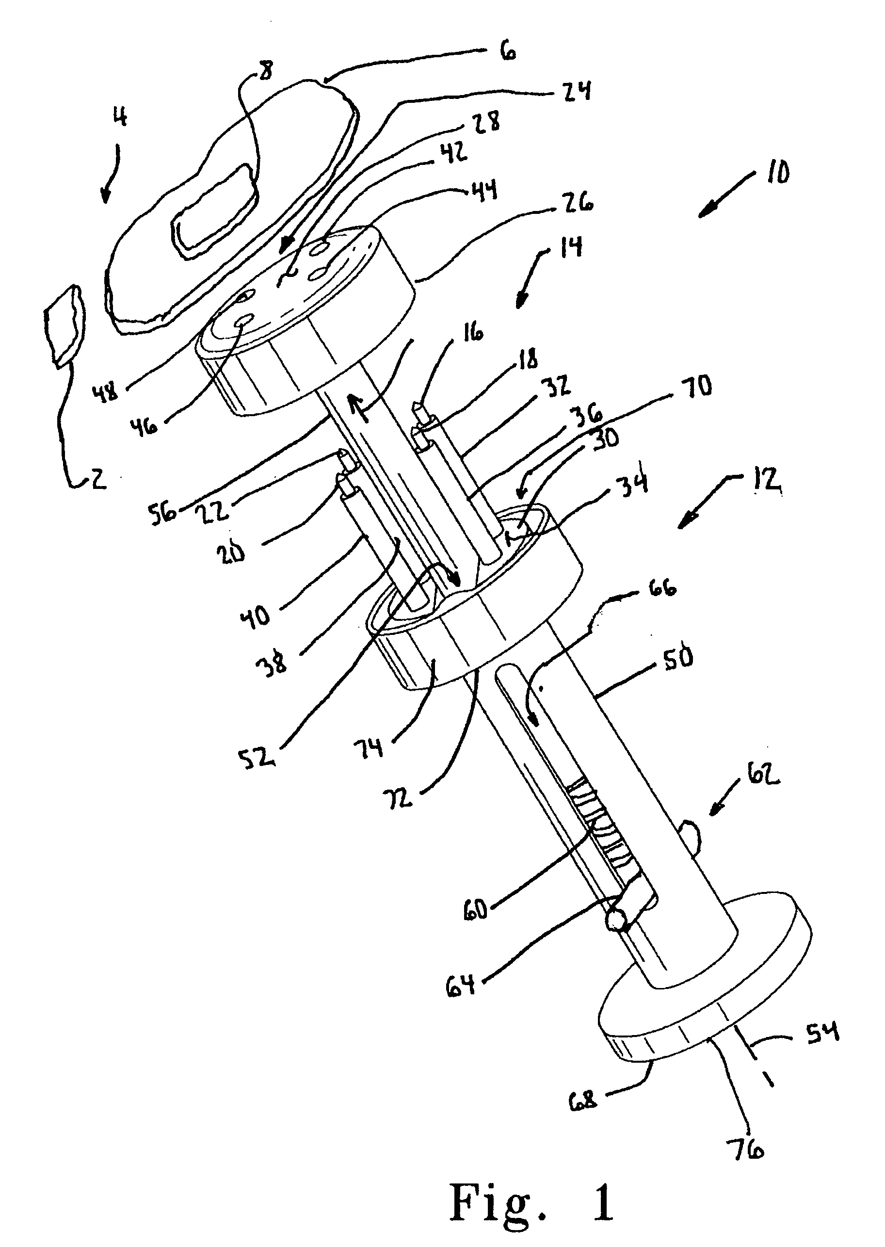
[0072] According to the present invention, referring now to FIG. 1, a suture anchor delivery device 10 is shown. The suture anchor delivery device 10 is adapted for use in performing surgery on tissue 2 of patient 4. The suture anchor delivery device 10 includes an applicator 12 and a cartridge 14. The cartridge 14 is removably secured to the applicator 12. An anchor 16 is removably associated with the cartridge 14. The suture anchor delivery device 10 of FIG. 1 may be utilized to secure a solitary anchor 16 or may be used for multiple anchors. It should be appreciated that the use for a single anchor with the use of a cartridge may have value, such as easy anchor replacement or accurate anchor placement with the delivery device.

[0073] For example, and refe...


PUM


Abstract

A suture anchor cartridge holder for use with an anchor cartridge in performing surgery on tissue of a patient is provided. The suture anchor cartridge holder includes a body that is adapted to receive at least a portion of the anchor cartridge. The suture anchor cartridge holder also includes a guide operatively associated with the body and adapted to receive at least a portion of the anchor cartridge.

Description

CROSS-REFERENCE TO RELATED APPLICATIONS [0001] Cross reference is made to the following applications: DEP5495 titled, “CARTRIDGE SUTURE ANCHOR DELIVERY DEVICE, SUTURE ANCHOR DELIVERY DEVICE AND ASSOCIATED METHOD” and DEP5605 titled “MULTIPLE SUTURE ANCHOR DELIVERY DEVICE, SUTURE ANCHOR DELIVERY KIT AND ASSOCIATED METHOD” filed concurrently herewith which are incorporated herein by reference. TECHNICAL FIELD OF THE INVENTION [0002] The present invention relates generally to the field of orthopaedics, and more particularly, to an implant for use in arthroplasty. BACKGROUND OF THE INVENTION [0003] The skeletal system includes many long bones that extend from the human torso. These long bones include the femur, fibula, tibia, humerus, radius and ulna. [0004] A joint within the human body forms a juncture between two or more bones or other skeletal parts. The ankle, hip, knee, shoulder, elbow and wrist are just a few examples of the multitude of joints found within the body. As should be...

Claims


Application Information

Patent Timeline
Patent Type & Authority Applications(United States)
IPC IPC(8): A61F2/00
CPCA61B17/0401A61B17/0642A61B17/105A61B17/1635A61B19/026A61B2017/0409A61B2017/0414A61B2017/0416A61B2017/0472A61B2017/0641A61B50/30
Inventor DEFFENBAUGH, DAREN L.PEDROZO, HUGO A.BISS, MATTHEW M.
Owner DEPUY PROD INC
Why Eureka
Try Eureka