
Manually guided suction apparatus

a suction apparatus and guided technology, applied in the direction of cleaning equipment, cleaning filter means, turf growing, etc., can solve the problems of limiting the filling capacity and adversely affecting the ability to handle the suction apparatus, and achieve the effect of avoiding leakage streams

Inactive Publication Date: 2007-05-10
ANDREAS STIHL AG & CO KG
View PDF5 Cites 19 Cited by
  • Summary
  • Abstract
  • Description
  • Claims
  • Application Information

AI Technical Summary

Benefits of technology

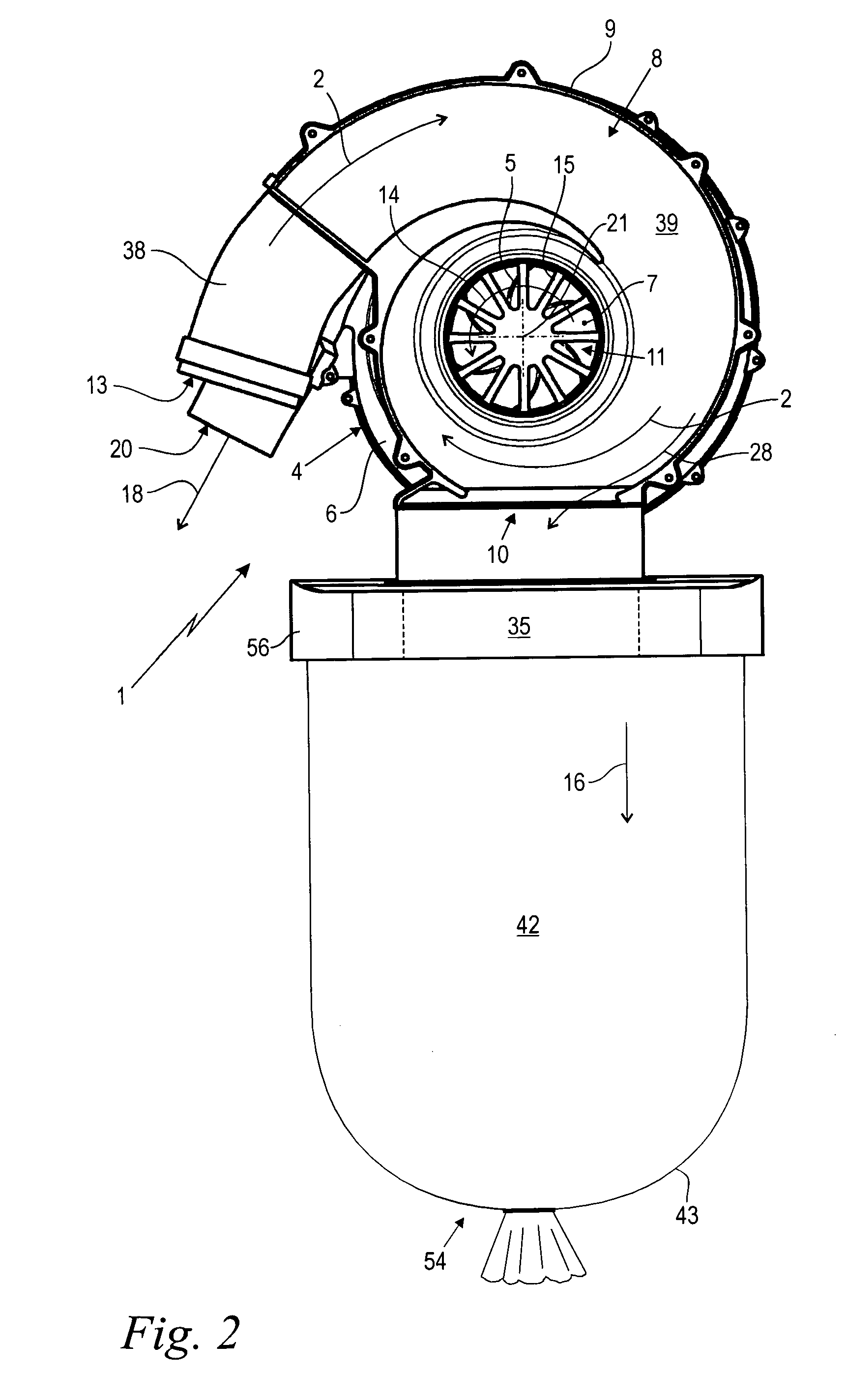
[0018] It has been shown that with an appropriate configuration of the removal opening in the intake channel, a removal of the sucked-up material from the suction air stream can be effected without having to guide the suction air stream itself into the collection bag or through it. By utilizing the force of gravity and / or the centrifugal force where a curved path is provided for the suction air stream, a separation can essentially be produced using only the inertial forces that occur. The lack of a noticeable air stream in the collection bag makes it possible to close off the bag in an essentially flow-tight manner without having to provide a complicated shaped support for the expansion of the collection bag. Depending upon the configuration of the suction apparatus, an inner pressure can be obtained in the collection bag that, although it deviates from the atmospheric pressure, does not produce a significant pressure differential. By using simple shape-imparting means, or merely by means of the sucked-up material that enters, the collection bag maintains is volumetric shape with a large receiving capacity.
[0031] To increase the removal efficiency, the removal opening in the customary operating position expediently faces in the gravitational direction. Added to the centrifugal forces acting upon the sucked-up material, in the region of the removal opening, is the force of gravity, which enhances a complete discharge of the sucked-up material out of the removal opening.

Problems solved by technology

Shape imparting and supporting containers, which adversely affect the ability to handle the suction apparatus and limit the filling capacity, are not required.

Method used


Image

  • Manually guided suction apparatus
  • Manually guided suction apparatus
  • Manually guided suction apparatus

Examples


Embodiment Construction

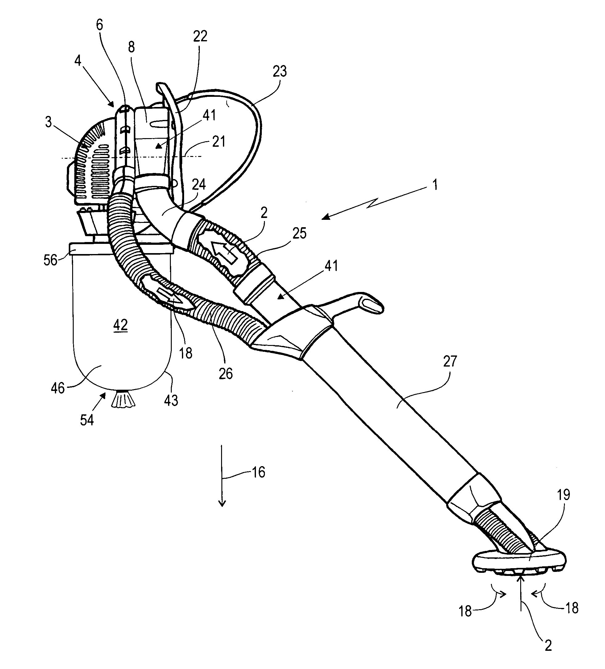
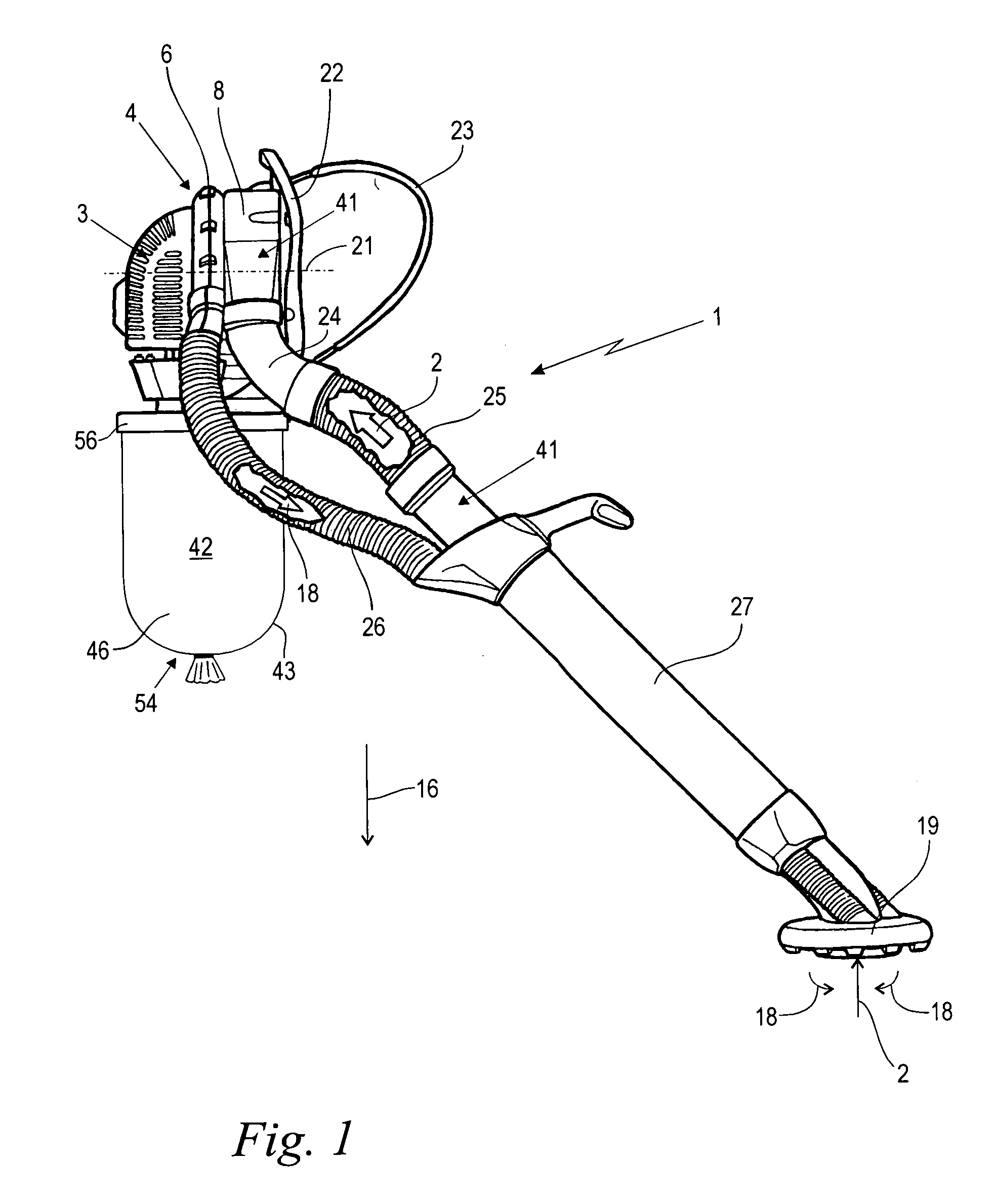
[0033] Referring now to the drawings in detail, FIG. 1 shows a side view of a manually-guided or portable suction apparatus 1 that is designed for being carried on the back of an operator and serves for suctioning up material by means of a suction air stream 2. The suction apparatus 1 includes a drive motor 3, which is not illustrated in detail, is disposed in a housing, and drives a suction fan 4. In the illustrated embodiment, the drive motor is an internal combustion engine, but could also be an electric motor or the like. The suction fan 4 is embodied as a radial fan that is provided with a horizontal axis of rotation 21. An axial fan could also be expedient. Disposed between the suction fan 4 and a backpack 22 having a carrying strap 23 is a centrifugal separator 8, an end face of which is flanged onto that side of a fan housing 6 of the suction fan 4 that is disposed opposite the drive motor 3.

[0034] During operation, a suction nozzle 19, which is secured to a free end of a g...


PUM


Abstract

A manually guided suction apparatus for suctioning up material via a suction air stream, comprising a suction fan having a fan housing surrounding a fan wheel and provided with an intake opening. A removal opening for sucked up material is disposed upstream of the intake opening in an intake channel that guides the suction air stream toward the suction fan. The removal opening empties into a collection bag, and the suction air stream in the intake channel is guided past the removal opening. An endless tube folded up to form a supply portion is stored in a storage chamber. A container portion of the endless tube forms the collection bag. A weight support for the collection bag prevents the supply portion from being pulled out of the storage chamber.

Description

[0001] The instant application should be granted the priority date of Nov. 10, 2005 the filing date of the corresponding German patent application 10 2005 053 620.4. BACKGROUND OF THE INVENTION [0002] The present invention relates to a manually guided suction apparatus for suctioning up material via a suction air stream. [0003] Manually guided suction apparatus are used in particular as devices in parks and gardens that can be carried on the back for suctioning up material in the form of dirt, refuse, leaves, or the like. Another application is the collection of small fruits, such as nuts, olives or the like. [0004] A suction fan that is driven by a drive motor draws in an air stream and blows it back out as a discharge air stream. In a known construction, a venturi device is disposed in the discharge air stream for producing an underpressure therein, thereby generating a suction air stream for sucking up the material. The material that is sucked up is conveyed into a collection bag...

Claims


Application Information

Patent Timeline
Patent Type & Authority Applications(United States)
IPC IPC(8): A47L5/14
CPCA01G1/125A47L5/14A47L5/36A47L9/1418A47L9/1427E01H1/0863A01G20/47
Inventor MAIER, GEORQZWIMPFER, MARKUSGAESE, UWE
Owner ANDREAS STIHL AG & CO KG
Learn More