Clutch-purpose hydraulic servo

a hydraulic servo and clutch technology, applied in mechanical actuator clutches, mechanical equipment, gearing, etc., can solve the problems of reducing affecting assembly ease, etc., to reduce production process and production cost, improve assembly ease, and reduce production process

Active Publication Date: 2007-05-10
TOYOTA JIDOSHA KK
View PDF4 Cites 6 Cited by
  • Summary
  • Abstract
  • Description
  • Claims
  • Application Information

AI Technical Summary

Benefits of technology

[0015] In the clutch-purpose hydraulic servo according to a sixth aspect, the stopper device is a step portion formed in the drum member of the second clutch. Therefore, the process of mounting a member as a stopper device can be eliminated. Hence, it becomes possible to improve the ease of assembly and reduce the production process and the production cost.
[0016] In the clutch-purpose hydraulic servo according to a seventh aspect, the step portion is formed on an inner peripheral side of an outer peripheral portion of the drum member of the second clutch. Therefore, for example, when splines for spline-mating the drum member of the second clutch and the drum member of the first clutch are formed on the inner peripheral side of the outer peripheral portion of the drum member of the second clutch and an outer peripheral side of the drum member of the first clutch, the step portion can simultaneously be formed. Hence, the production process can be reduced.
[0017] In the clutch-purpose hydraulic servo according to an eighth aspect, the step portion is formed on an outer peripheral side of an inner peripheral portion of the drum member of the second clutch. Therefore, although in some cases a piston member of the second clutch is provided with a (penetrating) cutout in order to achieve contact between the outer peripheral portion of the drum member of the second clutch and an outer peripheral portion of the drum member of the first clutch, this aspect eliminates the need to form such a cutout. Therefore, the step portion can easily be formed in the production process.
[0018] In the clutch-purpose hydraulic servo according to a ninth aspect, the stopper device is a snap ring fastened to the shaft member. Therefore, what is required is a relatively easy process of merely attaching a snap ring, as compared with a process of integrating the cylinder member and the shaft member by, for example, welding or the like. Thus, it becomes possible to improve the ease of assembly and reduce the production process and the production cost.
[0019] The clutch-purpose hydraulic servo according to a tenth aspect is used in a vehicular automatic transmission. Therefore, it becomes possible to improve the ease of assembly of the vehicular automatic transmission and reduce the production process and the production cost thereof.

Problems solved by technology

However, the integration of the member having a cylinder portion with the member that undergoes the same rotation through fixation thereof by, for example, welding or the like, requires a welding process (integrally forming process) or the like in the assembly of a clutch (automatic transmission), and therefore has the problem of impeding improvement in the ease of assembly and reduction of the production process and the production cost.

Method used


Image

  • Clutch-purpose hydraulic servo
  • Clutch-purpose hydraulic servo
  • Clutch-purpose hydraulic servo

Examples


first embodiment

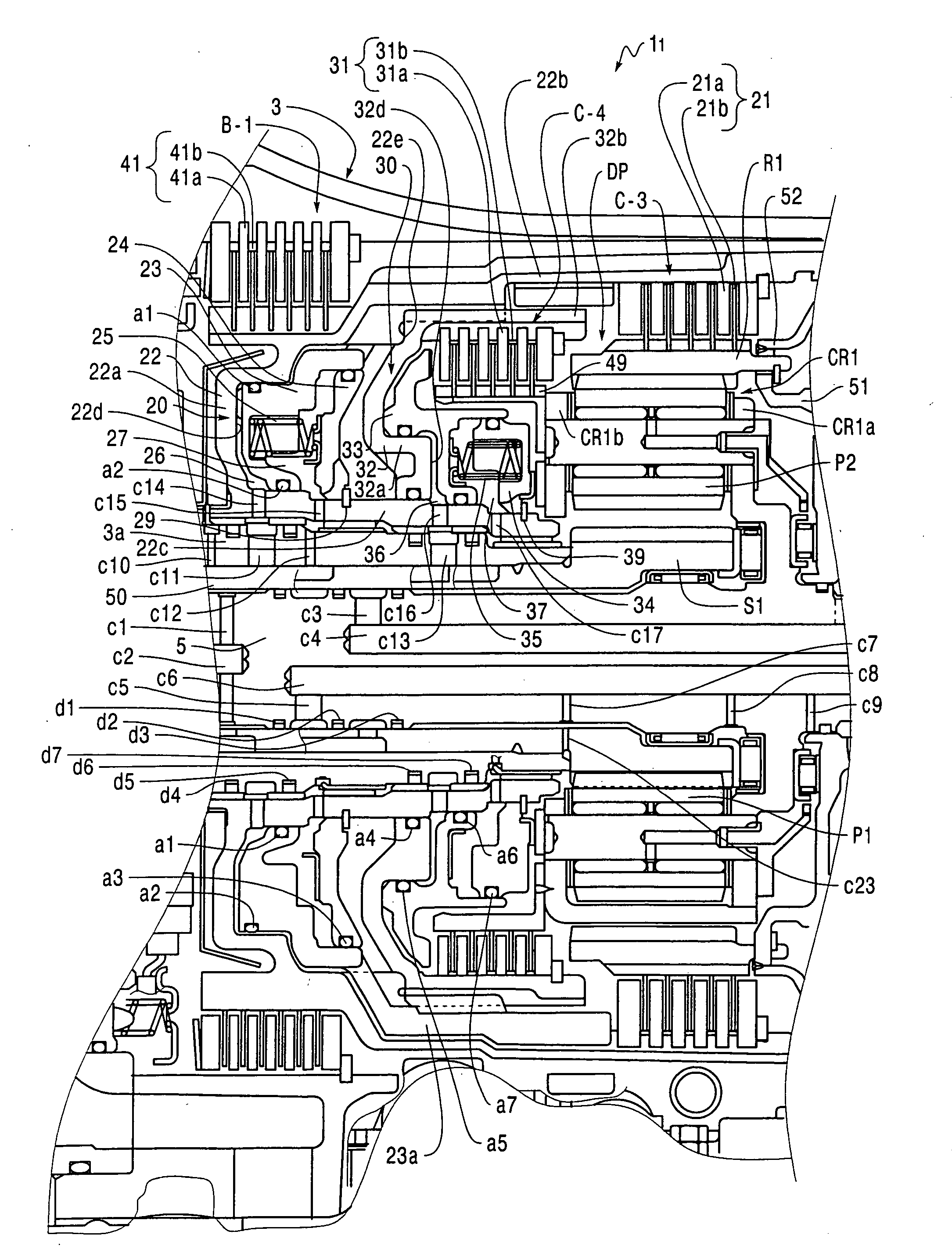
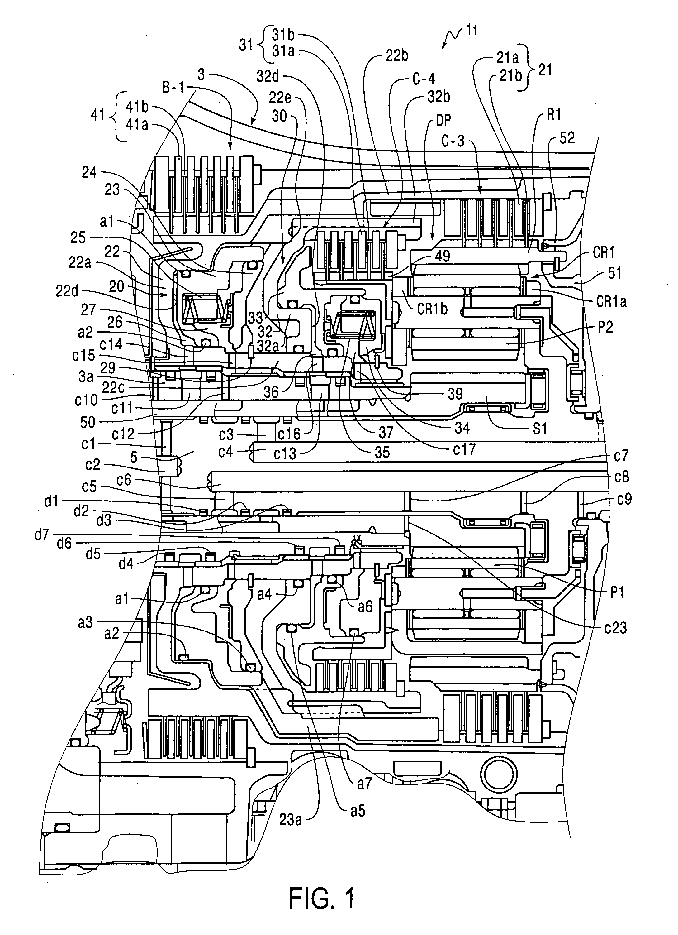
[0025] A first exemplary embodiment will be described hereinafter with reference to FIG. 1. FIG. 1 is a sectional view showing a portion of an automatic transmission 11 according to the

[0026] In the following description, the upward, downward, leftward and rightward directions in FIG. 1 correspond to the actual upward, downward, forward and rearward directions, respectively, with respect to a real vehicular automatic transmission (which will also be simply referred to as an “automatic transmission” below) 11. Furthermore, a direction along the length of an input shaft 5 will be referred to as an “axial direction”, and a direction orthogonal to the axial direction will be referred to as a “radial direction”. With regard to the position in a radial direction, a side relatively close to the input shaft 5 will be referred to as a “radially inward side (inner peripheral side)” and a side relatively remote from the shaft will be referred to as a “radially outward side (outer peripheral si...

second embodiment

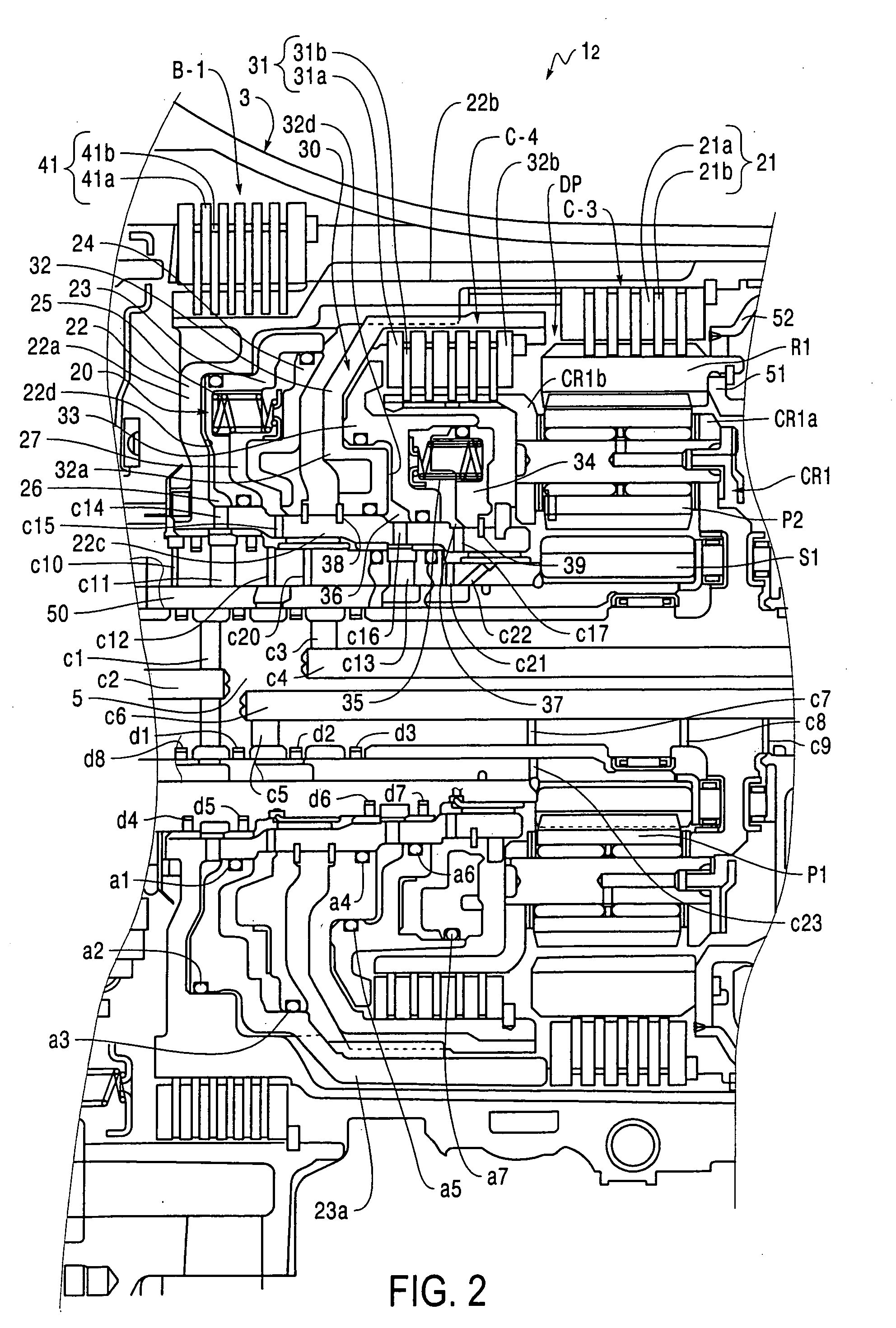
[0078] In the second embodiment, the device for restricting the forward movement of the clutch drum (cylinder member) 32 provided with the cylinder portion 32d is not the step portion 22e of the clutch drum 22, but is a snap ring 38 provided on an outer peripheral side of the hub portion 22c of the clutch drum 22.

[0079] The forward carrier plate CR1b of the carrier CR1 extends forward, and is spline-mated with the inner friction plates 31b of the clutch C-4 (i.e., the forward carrier plate CR1b and the hub member 49 in the first embodiment are formed integrally as a unit). Furthermore, as oil passages for supplying the lubricating oil from the oil passage within the boss portion 3a (within the sleeve member 50), oil passages c20, c21, c22 are bored in the boss portion 3a.

[0080] Thus, the snap ring 38 restricts forward movement of the clutch drum 32 with respect to the clutch drum 22. Furthermore, similar to the first embodiment, the second embodiment is structured so that the force...

fourth embodiment

[0108] In the fourth embodiment, the device for restricting the forward movement of the clutch drum (cylinder member) 32 provided with the cylinder portion 32d is a step portion 22f formed on an outer peripheral side of the hub portion (inner peripheral portion) 22c of the clutch drum 22.

[0109] The clutch drum 32 of the clutch C-4 has a hub portion 32c that extends in such a fashion as to fit over an outer peripheral side of the hub portion 22c of the clutch drum 22 of the clutch C-3. An inner peripheral side of a distal end portion of the hub portion 32c and an outer peripheral side of a distal end portion of the hub portion 22c are provided with splines and are spline-mated with each other. Therefore, the operating oil chamber 36 of the hydraulic servo 30 of the clutch C-4 is supplied with the operating oil from the oil passage c13 of the boss portion 3a via the oil passage c16 of the clutch drum 22 and an oil passage c30 of the clutch drum 32. A gap between the clutch drum 22 and...


PUM


Abstract

In a hydraulic servo for a clutch, a cancel plate is disposed on a second clutch drum that undergoes the same rotation as a second clutch drum provided with a cylinder portion, in such a fashion that the cancel plate is restricted from moving to a side opposite from a return spring in an axial direction. The first clutch drum is disposed, as a separate member, on the second clutch drum. A step portion of the second clutch drum prevents the first clutch drum from moving to a side opposite from the cancel plate. Due to the spring force of the return spring, the oil pressure in the cancel oil chamber and the oil pressure in the operating oil chamber, the force that presses the first clutch drum to the step portion is always greater than the force that presses the first clutch drum to the cancel plate side.

Description

[0001] This is a Continuation of Application Ser. No. 11 / 017,061 filed Dec. 21, 2004. The disclosure of the prior application is hereby incorporated by reference herein in its entirety. INCORPORATION BY REFERENCE [0002] The disclosures of Japanese Patent Applications Nos. 2004-319782 filed on Nov. 2, 2004 and JP 2003-431610 filed on Dec. 25, 2003, including the specification, drawings and abstract are incorporated herein by reference in their entireties.BACKGROUND [0003] 1. Field [0004] The disclosure relates to a hydraulic servo of a clutch for performing and discontinuing power transfer which is for use in, for example, vehicular automatic transmissions and the like. More particularly, the disclosure relates to a clutch-purpose hydraulic servo in which a drum member is disposed as a separate member on a shaft member. [0005] 2. Description of the Related Art [0006] Generally, in a hydraulic servo of a clutch for use in, for example, a vehicular automatic transmission or the like, a...

Claims


Application Information

Patent Timeline
Patent Type & Authority Applications(United States)
IPC IPC(8): F16D25/0638F16D25/10F16D25/063F16H3/66F16H63/30
CPCF16D25/0638F16H3/66F16H63/3026
Inventor AOKI, TOSHIHIKOFUJIMINE, TAKUYATODO, MINORUOZAKI, KAZUHISAOTA, HIROFUMIHOSHINO, AKIRATABATA, ATSUSHIABE, AKIHARUKINOSHITA, MASAFUMIHONDA, ATSUSHINOZAKI, KAZUTOSHI
Owner TOYOTA JIDOSHA KK
Why Eureka
Try Eureka