Mobile conveying and stacking system for multilayer dumping and process for operating the system

Inactive Publication Date: 2007-05-10
MAN TAKRAF FORDERTECHN
View PDF14 Cites 18 Cited by
  • Summary
  • Abstract
  • Description
  • Claims
  • Application Information

AI Technical Summary

Benefits of technology

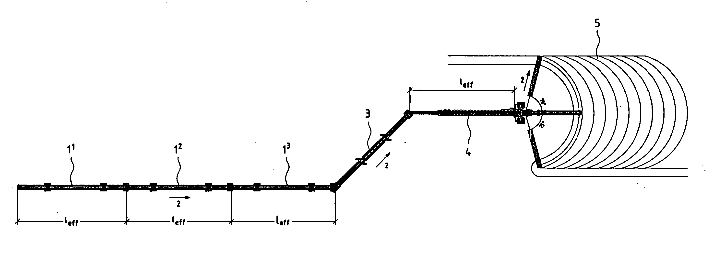
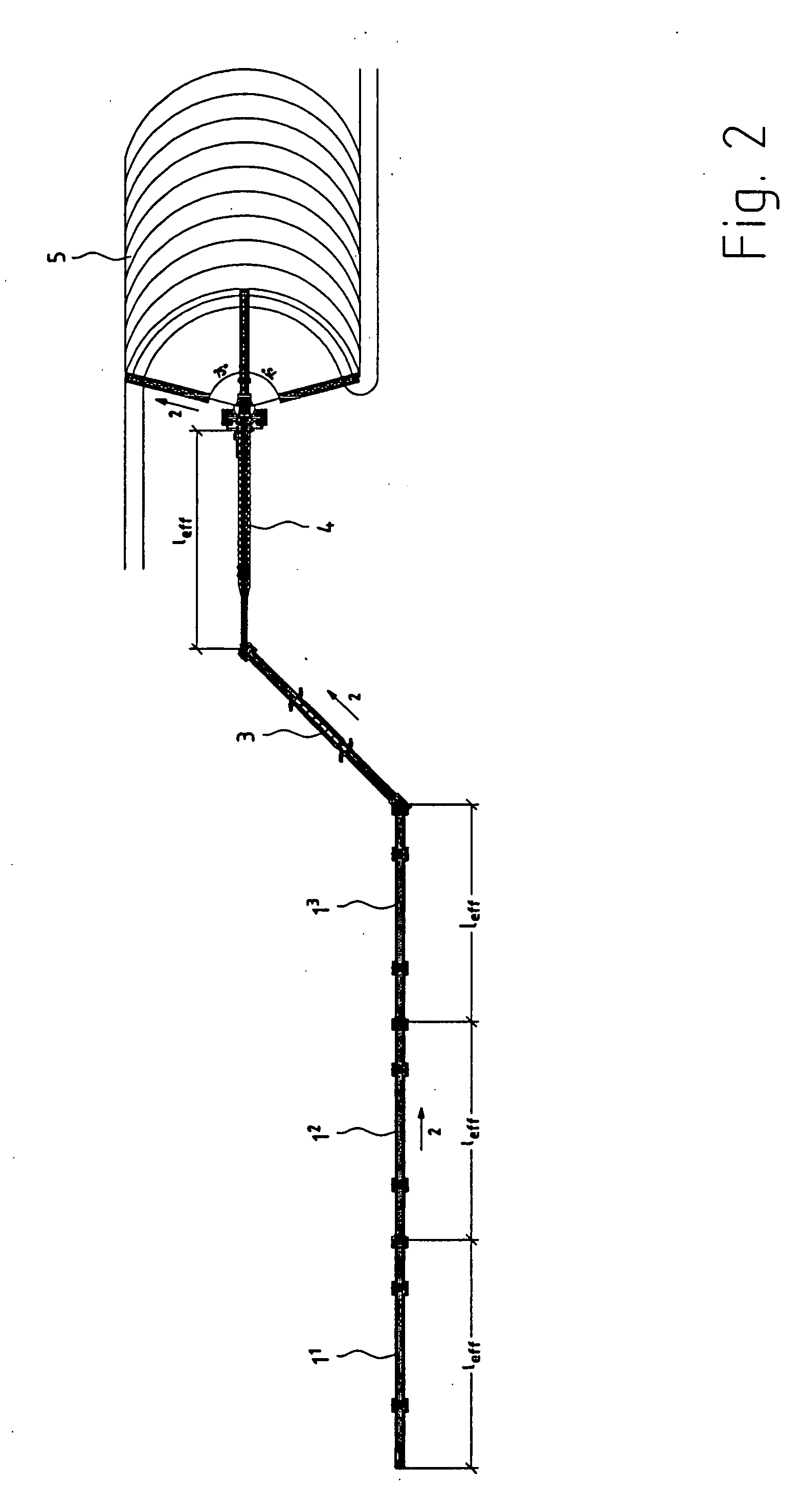
[0007] Each of the self-propelled standard grasshoppers has a great effective length of 75 m to 100 m. The self-propelled transfer grasshopper has approximately the same length and stands normally at an angle of 30° to 60° to the special stacker. The self-propelled special stacker is equipped with a long feed bridge, which also acts as a conveying bridge, and with a swingable stacker boom. The feed length on the feed bridge, which also acts as a conveying bridge, must correspond here to the effective length of the standard grasshoppers and the stacker boom must be so long that the block volume of a dumping length between two transfers corresponds to a daily output. The direction of conveying of the standard grasshoppers is parallel to the direction of conveying of the special stacker in the top view. The transfer grasshopper is provided to bridge over this parallel distance. It therefore stands at an angle of about 30° to 60° between these two conveying paths, which are offset in relation to one another. As a result, the

Problems solved by technology

The wear of the chassis is low

Method used


Image

  • Mobile conveying and stacking system for multilayer dumping and process for operating the system
  • Mobile conveying and stacking system for multilayer dumping and process for operating the system
  • Mobile conveying and stacking system for multilayer dumping and process for operating the system

Examples


Embodiment Construction

[0034] Referring to the drawings in particular, FIG. 2 shows a mobile conveying and dumping system, which is provided for piling up ore in layers of a height between 5 m and 10 m. The dimensions of a leach pad may be very large, the length and the width may reach up to a few thousand m. The mobile conveying and dumping system comprises, depending on the length of the leach pad, such a number of standard grasshoppers 1 as is necessary for operating the mobile conveying and stacking system for the multilayer dumping of ore. These standard grasshoppers form a conveying chain. The number of standard grasshoppers 1 was limited to three in the drawing. In fact, a larger number of grasshoppers 11 through 1n is needed to fill up a leach pad. A transfer grasshopper 3 and a special stacker 4 are also arranged downstream of these three standard grasshoppers 11 through 103 used in the direction of conveying 2. The ore is transferred from a conveyor, not shown in the drawing, onto the first stan...


PUM


Abstract

To leach the metal, crushed ore must be dumped in relatively thin layers of a height of approx. 5 m to 10 m. A conveying and stacking system, including a movable conveyor belt system, traveling tripper and stacker is used for this. The movable conveyor belt system is formed by a plurality of individual belts, the so-called grasshoppers. Provisions are made in the dumping technology for a high block for the end device in the conveying chain, the stacker with its swingable stacker boom, to always discharge an arc-shaped layer of ore, after which the device moves back by the amount of the next layer to be discharged in an arc-shaped pattern. This process is repeated until the stacker has moved back by the effective length of a grasshopper. Conveying is then stopped, one grasshopper is removed from the conveyor belt system and dumping of the ore is then continued. To enable this technology to be used, the stacker must be provided with a material pickup area, which is as long as a grasshopper. Furthermore, the material pickup must take place laterally from the direction of conveying of the stacker to ensure that the stacker is not hindered during the moving back. A transfer grasshopper is provided for this purpose, which stands in the direction of conveying at an angle of approx. 30° to 60° in relation to the main direction of conveying of the stacker. To enable the individual devices of the system to perform the movement intended for them, they are equipped with individually driven and steerable caterpillar-type chassis.

Description

CROSS REFERENCE TO RELATED APPLICATIONS [0001] This application claims the benefit of priority under 35 U.S.C. § 119 of German Patent Application DE 10 2005 053 586.0 filed Nov. 10, 2005, the entire contents of which are incorporated herein by reference. FIELD OF THE INVENTION [0002] The present invention pertains to a combination of devices for a mobile conveying and stacking system for the multilayer dumping of ore on a leach pad and to a process for operating this system. BACKGROUND OF THE INVENTION [0003] To leach the metal, crushed ore must be dumped in relatively thin layers with a height of about 5 m to 10 m. Each of these layers consists of a plurality of high blocks arranged next to one another. In case of large leach pads, this dumping operation is carried out by a conveying and stacking system, comprising a movable conveyor belt system, traveling tripper and radial stacker. The progress of dumping is relatively great because of the low dumping height. This technology for ...

Claims


Application Information

Patent Timeline
IPC IPC(8): B65G37/00
CPCB65G41/008B65G65/28
Inventor HOFFMANN, DIETER
Owner MAN TAKRAF FORDERTECHN
Why Eureka
Try Eureka