Height Control Valve For Vehicle Axle/Suspension System

a technology of suspension system and axle, which is applied in the direction of process and machine control, transportation items, instruments, etc., can solve the problems of reducing the ability of the compressed air reservoir to rapidly re-inflate the air spring when required, and the ride is relative rough

Active Publication Date: 2007-05-10
HENDRICKSON USA L L C
View PDF11 Cites 17 Cited by
  • Summary
  • Abstract
  • Description
  • Claims
  • Application Information

AI Technical Summary

Benefits of technology

[0018] These objectives and advantages are also obtained by a second exemplary height control valve for an air spring of an air-ride axle/suspension system of a heavy-duty vehicle of the present invention. A second exemplary embodiment of the height control valve includes a valve body being in fluid communication with an air reservoir, with the air spring, and with atmosphere, actuation means operatively connected to the valve body and the axle/suspension

Problems solved by technology

Early suspension designs included heavy spring suspensions which resulted in a relatively rough ride to the caigo and did not allow loads to equalize among the axles in all situations, thus creating the need for a suspension system with soft ride characteristics and efficient equalization characteristics Ihe subsequent development of air suspension systems provided load equalization among multiple axles for semi-trailers as well as improved tide quality for individual axles.
However, height control valves of the prior art sometimes allow over-exhaustion of air from the air springs when the vehicle is loaded.
Then, when exhaustion of air from the air springs is necessary to maintain design ride height, the increased pressure in the air springs raises the rate of flow of air exiting the air springs through the height control valve.
Such a potentially increased rate of exhaust may enable too much compressed air to exit the air springs, thereby reducing the ability of the compressed air reservoir to rapidly re-inflate the air springs when required.
Since height control valves of the prior art exhaust air at a rapid rate, when the air springs are under an increased load from a freight-laden vehicle, this pressure differential may be too small to enable the vehicle air reservoir to provide sufficient compressed air to the air springs for regaining and maintaining design ride height in certain instances.
Thus, for a loaded vehicle, when the axle/sus

Method used


Image

  • Height Control Valve For Vehicle Axle/Suspension System
  • Height Control Valve For Vehicle Axle/Suspension System
  • Height Control Valve For Vehicle Axle/Suspension System

Examples


Embodiment Construction

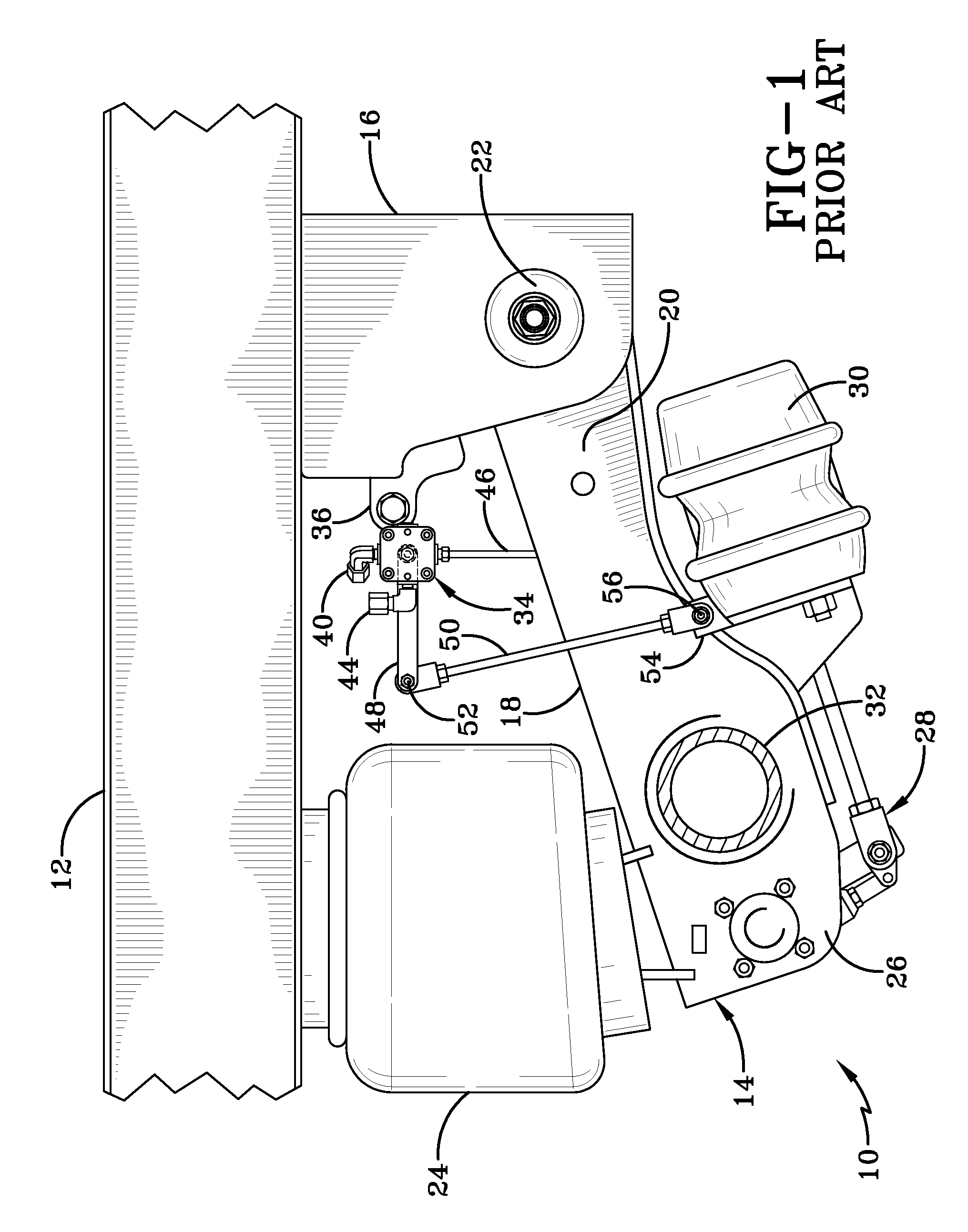
[0029] So that the structure, operation, and advantages of the improved height control valve for an air spring of an axle / suspension system of a heavy-duty vehicle can be best understood, a prior art height control valve 34 for an air spring is shown in FIG. 1 mounted on an air-ride axle / suspension system, indicated generally at 10, which in turn is mounted on a heavy-duty vehicle frame 12, and now will be described in the environment in which it is utilized. It is important to note that prior art air-ride axle / suspension system 10, while shown as a specific type of trailing arm axle / suspension system, also includes other types of heavy-duty vehicle air-ride suspension assemblies known to those skilled in the art, such as other types of trailing arm and leading arm air-ride suspension assemblies It also is important to note that vehicle frame 12 is generally representative of various types of frames used for heavy-duty vehicles, including primary frames that do not support a subfram...


PUM


Abstract

A height control valve for an air spring of an air-ride axle/suspension system of a heavy-duty vehicle includes a body. The valve body is pneumatically connected to an air reservoir of the vehicles an ail spring, and to atmosphere A control arm actuates the valve to direct air from the reservoir into the air spring, when air is to be added to the air spring When air is to be exhausted from the air spring, the valve, actuated by the control arm, directs air from the air spring to atmosphere The valve includes a throttle assembly that can regulate the rate of pneumatic flow from the air spring to atmosphere when the vehicle is loaded and the air spring is in an extended condition. A throttle assembly can also be used to regulate the rate of pneumatic flow from the air reservoir to the air spring.

Description

CROSS-REFERENCE TO RELATED APPLICATION [0001] This application claims the benefit of U.S. Provisional Patent Application Ser. No 60 / 733,745, filed Nov. 4, 2005.BACKGROUND OF THE INVENTION [0002] 1. Technical Field [0003] The present invention relates to the art of air-ride axle / suspension systems for heavy-duty vehicles, such as tractor-trailers or semi-trailers, which cushion the ride and stabilize the vehicle during operation. More specifically, the invention relates to pneumatic control of the air springs of an air-ride axle / suspension system, and in particular to a height control valve which regulates the flow of air out of the air springs. [0004] 2. Background Art [0005] Heavy-duty vehicles, such as tractor-trailers or semi-trailers, typically include one or more leading or trailing arm suspension assemblies that connect the wheel-bearing axles of the vehicle to the frame of the vehicle. Early suspension designs included heavy spring suspensions which resulted in a relatively r...

Claims


Application Information

Patent Timeline
IPC IPC(8): B60G11/26B60G17/00F16K11/074
CPCB60G9/003B60G11/27B60G17/0525B60G2200/31B60G2202/152B60G2204/116B60G2204/20B60G2600/85Y10T137/86911Y10T137/2544
Inventor PIERCE, PHILLIPPI R.CERVANTEZ, JESSE
Owner HENDRICKSON USA L L C
Why Eureka
Try Eureka