Eureka AIR delivers breakthrough ideas for toughest innovation challenges, trusted by R&D personnel around the world.

Ground testing method and apparatus

Inactive Publication Date: 2007-05-10
MAGICGROUND TECH
View PDF24 Cites 11 Cited by
  • Summary
  • Abstract
  • Description
  • Claims
  • Application Information

AI Technical Summary

Benefits of technology

[0010] An advantage of the present invention is improved safety due to the ability to test the local grounding system of a tower without having to disconnect it completely from the utility neutral conductor.
[0011] Another advantage is the ability to conduct sufficient current to trip a circuit breaker, in the event of failures that would make the utility neutral “hot”.
[0012] Another advantage is the ability to block ground currents that interfere with testing of structure's local grounding systems.

Problems solved by technology

Communication towers include signal processing equipment that is particularly susceptible to noise generated from within the power system and grounding system for the tower.
Improper or poor electrical grounding can create personnel safety problems as well as interference with signal processing equipment.
Furthermore, tall towers attract lightning.
The high current of a lightning strike can cause extreme voltage changes if the grounding system does not have a low resistance to earth ground.
Attempts to use bandpass filters to permit 60 Hz current to flow through the grounding circuit while blocking 128 Hz current feedback through the electrical utility have been unable to filter out all of the test frequency signal.
During the fall of potential test the utility neutral must disconnected from the ground rod, as the current flow on the neutral will cause an inaccurate reading.
This eliminates the redundancy of independent grounding systems, and creates an unacceptable risk for communications companies.
This lack of redundancy creates a potential danger to personnel and equipment due to the possibility of potential differences between the two grounding systems.
Possible high voltage transients present a danger of electrical shock to personnel, who may inadvertently come into contact between the neutral bus and ground during a grounding system test, forming a replacement connection for the open ground to neutral connection.
Similarly, sensitive communications equipment power supplies are at risk of exposure to voltage and current in excess of their rated voltage and current due to a floating neutral voltage.

Method used


Image

  • Ground testing method and apparatus
  • Ground testing method and apparatus
  • Ground testing method and apparatus

Examples


Embodiment Construction

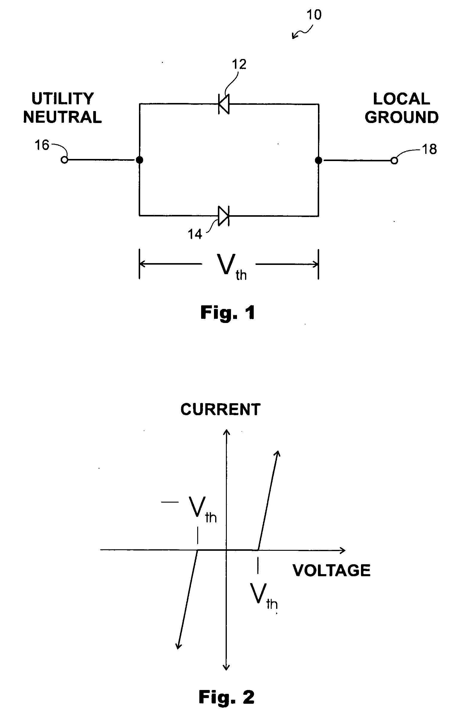
[0022] Referring first to FIG. 1, a basic circuit 10 applying the principle of the present invention is comprised of a pair of diodes 12, 14 connected in reverse parallel or antiparallel. When a voltage is applied across terminals 16&18, regardless of the polarity, current flows across the parallel diode path, provided that the voltage is equal to or greater than the forward bias voltage of the diodes. The forward bias voltage is an inherent property of all diodes. The forward bias voltage is defined as the voltage level required to forward bias the diode to a conductive state. Typically, the forward bias voltage of a single diode is very low, on the order of 0.7V, and may vary more or less according to the properties of the particular diode that is used. For the purpose of the present invention it is convenient to think of the forward bias voltage as a threshold voltage for conduction. Each single diode could be replaced by multiple diodes in series to increase threshold voltage an...


PUM


Abstract

The present invention is directed to a ground-current isolating circuit for providing a low voltage barrier between a service neutral conductor and an associated grounding system. The voltage barrier circuit comprises a first current unidirectional element and a second current unidirectional element connected in antiparallel. The unidirectional elements are preferably diodes having a characteristic threshold voltage. The current in a forward biased direction is blocked by the circuit until an applied forward biased voltage exceeds the threshold voltage. The present invention also is directed to a method of isolating a neutral conductor temporarily from an associated grounding system during testing of a structure grounding system. The method includes connecting a voltage barrier circuit in parallel with a conductor bonding the neutral conductor to the associated grounding system, then disconnecting the bonding conductor; conducting a test of the structure grounding system associated with the structure, and reconnecting the bonding conductor between the neutral conductor and grounding system.

Description

FIELD OF THE INVENTION [0001] The present invention is directed to a method and apparatus for testing grounding systems, and more particularly to a method and apparatus for testing grounding systems in communication towers by isolating the local ground from the utility neutral while simultaneously providing an effective safety ground. BACKGROUND OF THE INVENTION [0002] Communication towers include signal processing equipment that is particularly susceptible to noise generated from within the power system and grounding system for the tower. Improper or poor electrical grounding can create personnel safety problems as well as interference with signal processing equipment. Communication towers are generally equipped with power supplies for signal communications, controls, lighting, air conditioning and auxiliary equipment that may introduce transient voltages into the communications signals, particularly if not properly grounded. Furthermore, tall towers attract lightning. The high cur...

Claims


Application Information

Patent Timeline
IPC IPC(8): G01R31/14
CPCG01R31/025G01R31/52
Inventor GASTON, CHARLES A.SILAR, VAUGHN G. JR.
Owner MAGICGROUND TECH
Why Eureka
Eureka Blog
Learn More