Antenna system for tracking moving object mounted satellite and its operating method

an antenna system and satellite technology, applied in the direction of antennas, direction finders, movable body antenna adaptation, etc., can solve the problems of increasing the complexity of the system configuration, increasing the complexity of the system, and difficulty in implementing the antenna, so as to reduce the production cost

an antenna system and satellite technology, applied in the direction of antennas, direction finders, movable body antenna adaptation, etc., can solve the problems of increasing the complexity of the system configuration, increasing the complexity of the system, and difficulty in implementing the antenna, so as to reduce the production cost

US20070103366A1Inactive Publication Date: 2007-05-10WIWORLD

Image

  • Antenna system for tracking moving object mounted satellite and its operating method
  • Antenna system for tracking moving object mounted satellite and its operating method
  • Antenna system for tracking moving object mounted satellite and its operating method

Examples


Embodiment Construction

[0037] Now, preferred embodiments of the present invention will be described in detail with reference to the annexed drawings. In the drawings, the same or similar elements are denoted by the same reference numerals even though they are depicted in different drawings. In the following description, a detailed description of known functions and configurations incorporated herein will be omitted when it may make the,subject matter of the present invention rather unclear.

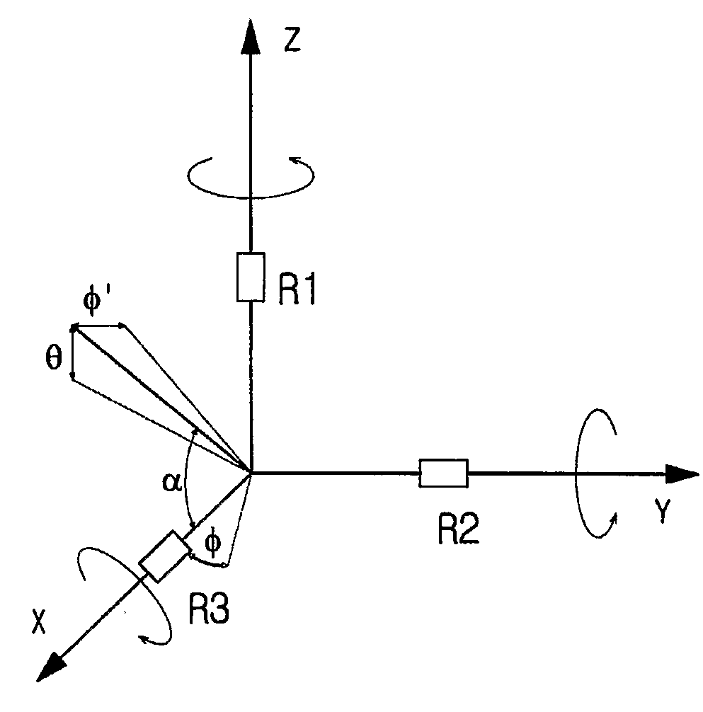
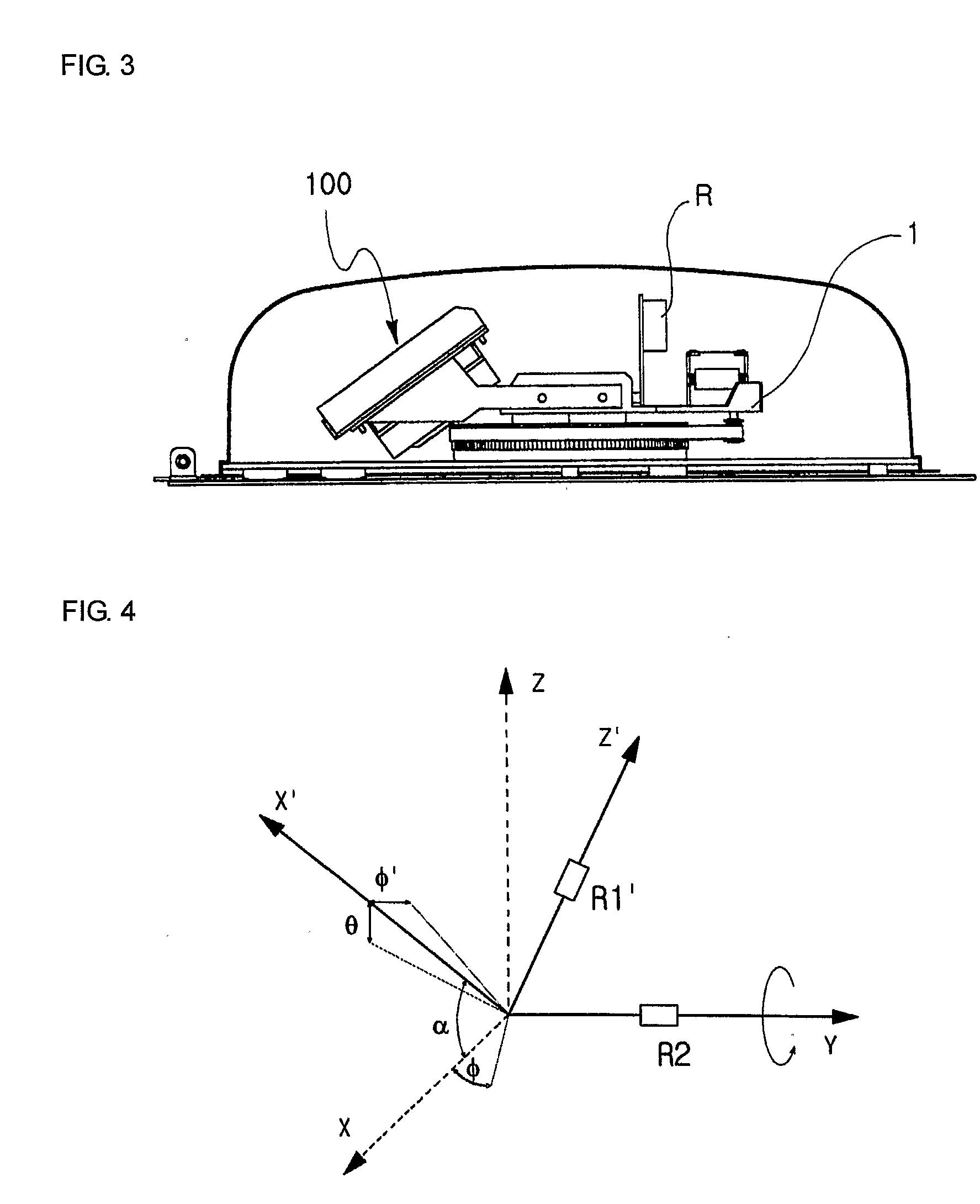
[0038]FIG. 4 is an installation conceptual diagram illustrating a satellite tracking antenna system including two gyro sensors to track a satellite position in accordance with the present invention. Prior to describing FIG. 4, a plurality of symbols shown in FIG. 4 will hereinafter be described:

[0039] X-axis: Center axis for detecting an angular velocity variable in a roll direction;

[0040] Y-axis: Center axis for detecting an angular velocity variable in a pitch direction;

[0041] Z-axis: Center axis for detecting an ...


PUM


Abstract

An improved satellite tracking antenna system mounted to a moving object and a method for operating the same detect and track elevation and azimuth angles of a satellite using only two gyro sensors in a two-axis satellite tracking antenna system, and detect and track an azimuth angle of the satellite using only one gyro sensor in a one-axis satellite tracking antenna system. The antenna system detects the satellite position using two gyro sensors, which are mounted to be orthogonal to each other to a planar axis perpendicular to a satellite-directed target point of the antenna, and continuously tracks the satellite position using a calibration algorithm without using additional absolute angle sensors, resulting in simplified system configuration and reduced production costs.

Description

TECHNICAL FIELD [0001] The present invention relates to an antenna system for tracking a satellite and a method for operating the same, and more particularly to an improved satellite tracking antenna system mounted to a moving object and a method for operating the same, which detect and track elevation and azimuth angles of the satellite using only two gyro sensors in a two-axis satellite tracking antenna system, and detect and track an azimuth angle of the satellite using only one gyro sensor in a one-axis satellite tracking antenna system. BACKGROUND ART [0002] Typically, an antenna system for tracking a satellite (hereinafter referred to as a satellite tracking antenna system) is classified into a one-axis antenna system, a two-axis antenna system, and a three-axis antenna system according to the number of motors capable of controlling an antenna direction to track the satellite. [0003] The one-axis antenna system fixes an elevation angle of an antenna, and controls only an azimu...

Claims


Application Information

Patent Timeline
10 May 2007
Publication
US20070103366A1
IPC
H01Q3/00; H01Q1/32; H01Q3/08
CPC
G01S3/42; H01Q1/1257; H01Q1/3275; H01Q3/08; H01Q3/10
Inventors
PARK, CHAN GOO