Stage unit and exposure apparatus

a technology applied in the field of stage units and exposure apparatuses, can solve the problems of affecting the apparatus, increasing power consumption, and reducing exposure accuracy, and achieve the effect of a degree of freedom in design and arrangement of the counterweigh

Active Publication Date: 2007-05-10
NIKON CORP
View PDF13 Cites 23 Cited by
  • Summary
  • Abstract
  • Description
  • Claims
  • Application Information

AI Technical Summary

Benefits of technology

[0019] With this stage unit, since the counterweight is divided into the first section placed in the first space and the second section placed in the second space that is different from the first space, a degree of freedom in design and a degree of freedom in arrangement of the counterweight improve, and in addition, the inner volume of the first space can be set smaller compared to the case when the entire counterweight is placed in one space.

Problems solved by technology

In particular, in the scanner, in order for a reticle stage and a wafer stage to perform acceleration, constant speed and deceleration respectively upon exposure, the vibration caused by a reaction force generated at a linear motor stator due to the acceleration / deceleration adversely affects the apparatus, in particular, an optical system, which causes the decrease in exposure accuracy.
For example, in an ArF excimer laser exposure apparatus or the like, the increase in size of the chamber leads to the increase in size of an air supply fan, a cooler, a heater, an air filter and the like that constitute an air-conditioner, and to the increase in power consumption, and for example, in an EUV exposure apparatus and an electron beam exposure apparatus, leads to the increase in size of a vacuum pump and other vacuum-related instruments and the increase in power consumption.
Also in an apparatus other than an exposure apparatus, the similar inconvenience occurs as far as the apparatus houses a stage inside a chamber or a space partitioned by a partition wall.

Method used


Image

  • Stage unit and exposure apparatus
  • Stage unit and exposure apparatus
  • Stage unit and exposure apparatus

Examples


Embodiment Construction

[0030] An embodiment of the present invention will be described as follows based on FIGS. 1 to 8.

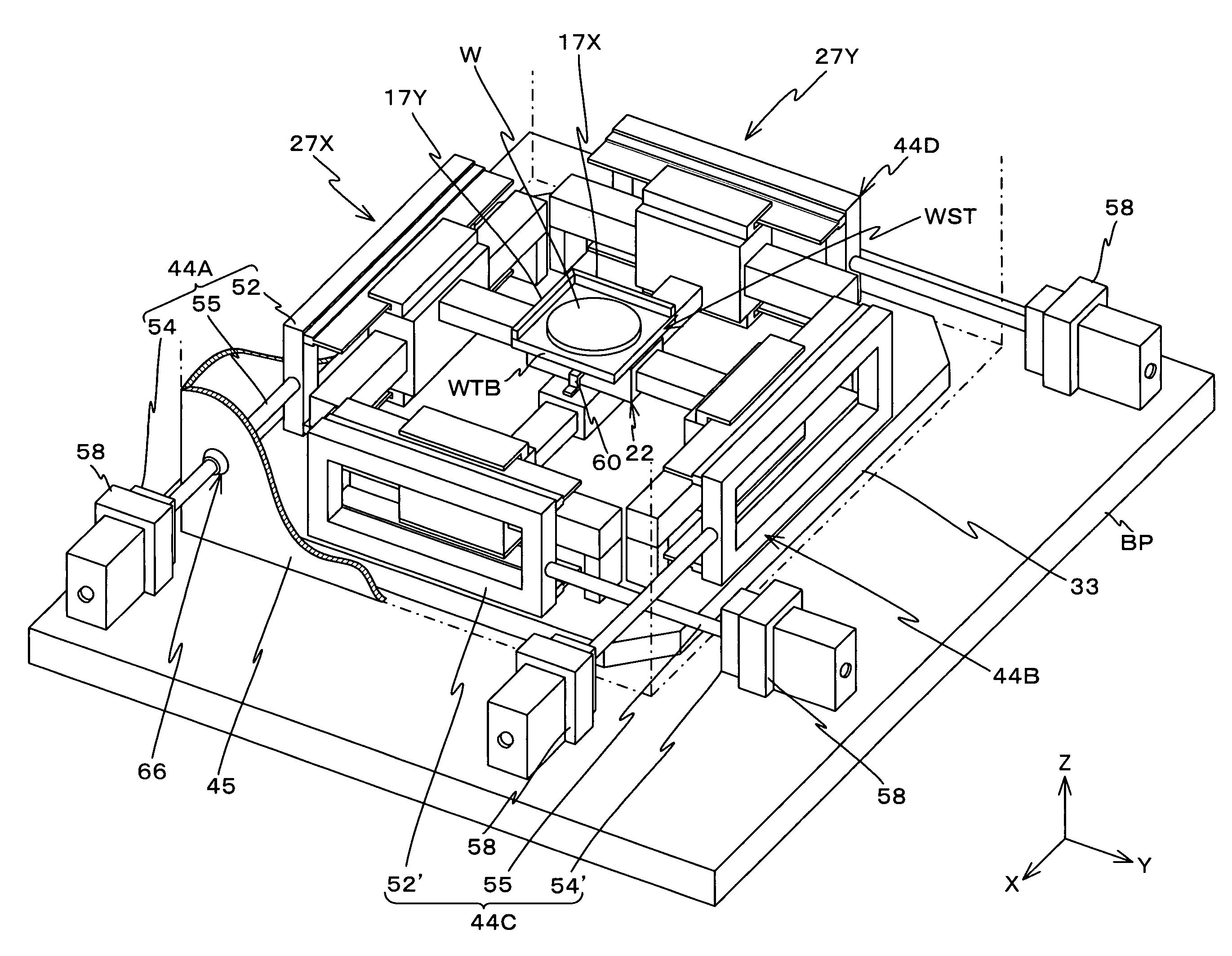
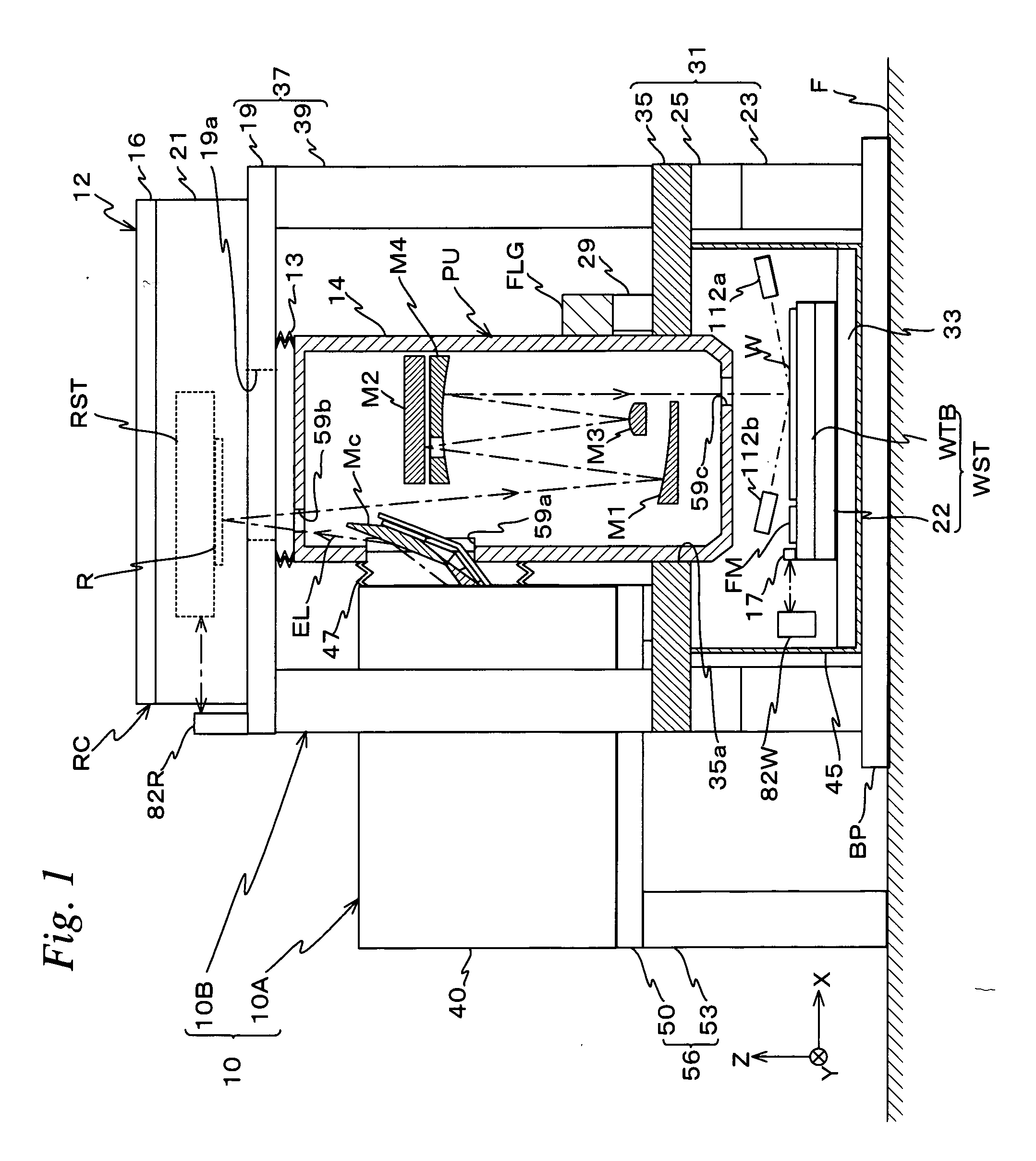
[0031]FIG. 1 schematically shows the entire configuration of an exposure apparatus 10 related to an embodiment. In FIG. 1, a sectional view of a part of exposure apparatus 10, more specifically, a sectional view of a projection unit PU and a wafer stage chamber 45 is shown in order to show an internal configuration.

[0032] In exposure apparatus 10, since projection unit PU, which has a projection optical system inside that projects a reflected beam from reticle R perpendicularly on a wafer W, is employed, in the following description, a projection direction of an illumination light from the projection optical system to wafer W is called as an optical axis direction of the projecting optical system, and also the description will be made assuming that the optical axis direction is a Z-axis direction, a horizontal direction in the page surface of FIG. 1 that is orthogonal to the optical ax...


PUM


Abstract

When a stage on which a wafer is mounted is driven in an X-axis direction by a liner motor, a reaction force of the drive force is generated at a stator and acts on a counterweight via the stator, and thereby the counterweight moves in a direction opposite to the stage in accordance with movement of the stage in the X-axis direction. Accordingly, the reaction force generated by the drive of the stage can substantially be canceled by the movement of the counterweight. Further, since the counterweight has a first section that is connected to the stator, and a second section that is separated from the first section in the X-axis direction and connected to the first section via a connection section, a partition wall of a chamber can be placed using the connected portion as a boundary, and the second section of the counterweight can be located outside the partition wall. Thus, a stage housing space can be set to smaller.

Description

CROSS-REFERENCE TO RELATED APPLICATIONS [0001] This application is a continuation of International Application PCT / JP2006 / 300143, with an international filing date of Jan. 10, 2006, the disclosure of which is hereby incorporated herein by reference in its entirety, which was not published in English. This non-provisional application also claims the benefit of Provisional Application No. 60 / 734,762 filed Nov. 9, 2005, the disclosure of which is hereby incorporated herein by reference in its entirety.BACKGROUND OF THE INVENTION [0002] 1. Field of the Invention [0003] The present invention relates to stage units and exposure apparatuses, and more particularly to a stage unit that is suitable as a stage that sets the position of a specimen of an exposure apparatus or other precision instruments, and to an exposure apparatus that is equipped with the stage unit. [0004] 2. Description of the Background Art [0005] Conventionally, in a lithography process for manufacturing a semiconductor d...

Claims


Application Information

Patent Timeline
Patent Type & Authority Applications(United States)
IPC IPC(8): G03B27/42
CPCG03F7/70716G03F7/70766
Inventor TANAKA, KEIICHI
Owner NIKON CORP
Why Eureka
Try Eureka