
Substrate support apparatus for use in a position measuring device

a technology of position measuring device and support apparatus, which is applied in the direction of optical devices, instruments, photomechanical apparatus, etc., can solve the problem of too strong variation of wavelength for the required measurement accuracy, and achieve the effect of improving repeatability

Inactive Publication Date: 2007-05-10
VISTEC SEMICON SYST
View PDF11 Cites 14 Cited by
  • Summary
  • Abstract
  • Description
  • Claims
  • Application Information

AI Technical Summary

Benefits of technology

[0013] There is therefore a need to improve the repeatability or more generally the measuring accuracy in the laser-interferometric determination of the position of a substrate held by a substrate support apparatus, and to uncouple it from external atmospheric influences.
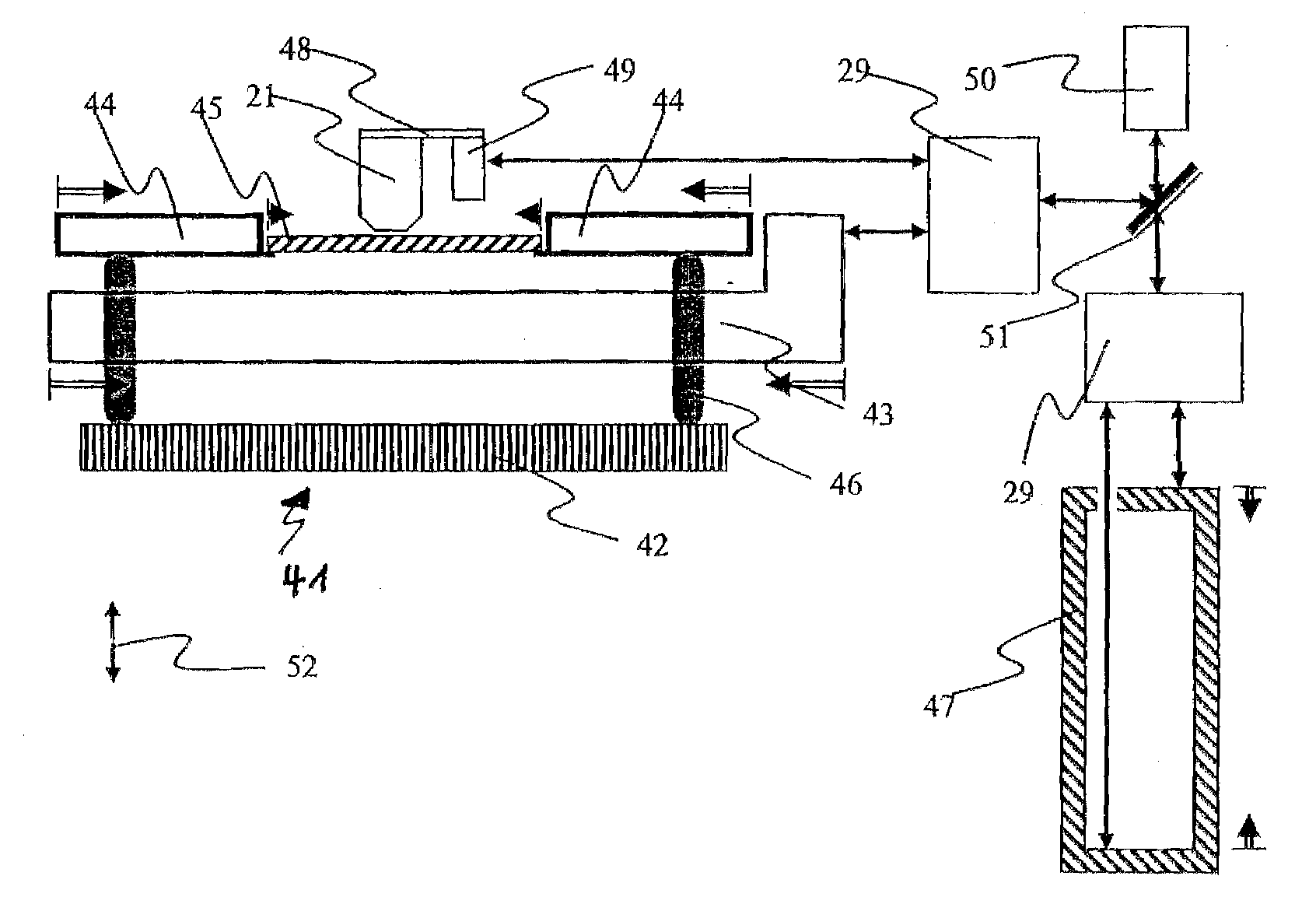
[0026] It has been found that in the above described construction of a substrate support apparatus with components of different moduli of elasticity a further effect occurs which negatively affects measuring accuracy. This effect may be illustrated with reference to FIG. 4. The figure schematically shows a substrate support apparatus 41 with a stage construction 42, a mirror body 43 arranged thereon, and a substrate 45 (e.g. a mask) arranged above it, and a substrate support 44 (e.g. a mask frame), wherein advantageously three connecting elements 46 (here connecting rods) are provided, extending through mirror body 43 in a vertical direction. A change in the air pressure basically has an effect on the substrate support apparatus in spherical symmetry. In most of the measuring devices changes in the vertical (z) are not critical since suitable compensation means (such as auto-focusing) are provided. Other deformations have an effect in the direction of the laser axes of the interferometer system and cause a change in the distance between mirror body 43 and substrate 45 (indicated with a double arrow). These effects have been discussed in detail above. Other effects which occur are “lever effects” which have been shown as arrows having double lines. As the air pressure is increased, mirror body 43 (Zerodur) will be deformed more noticeably than stage construction 42 (Invar), i.e. the two components will be offset from each other. This offset has an effect on the connecting elements 46 which will amplify this effect as levers. The forces caused hereby can compress substrate 45 and substrate support 44. Similarly, mask 45 will be more strongly deformed than mask frame 44. With larger forces and deformations, the static friction of each of the support points may be overcome, which may lead to a displacement of the substrate with respect to the substrate support, of the substrate support with respect to the mirror body and / or of the mirror body with respect to the stage construction.
[0027] These effects can be avoided by having the moduli of elasticity of the above components of the substrate support apparatus according to FIG. 4 tuned to each other, i.e. match each other as far as possible. Another possibility to reduce the above effects is by correspondingly setting the planes formed by stage construction 42, mirror body 43 and substrate support 44. The support points created by the three connecting elements 46 must be configured in such a way that the individual components do not stress each other.

Problems solved by technology

Despite the control of temperature and humidity in the climate chamber, the remaining variations of the wavelength are too strong for the required measuring accuracy.

Method used


Image

  • Substrate support apparatus for use in a position measuring device
  • Substrate support apparatus for use in a position measuring device
  • Substrate support apparatus for use in a position measuring device

Examples


Embodiment Construction

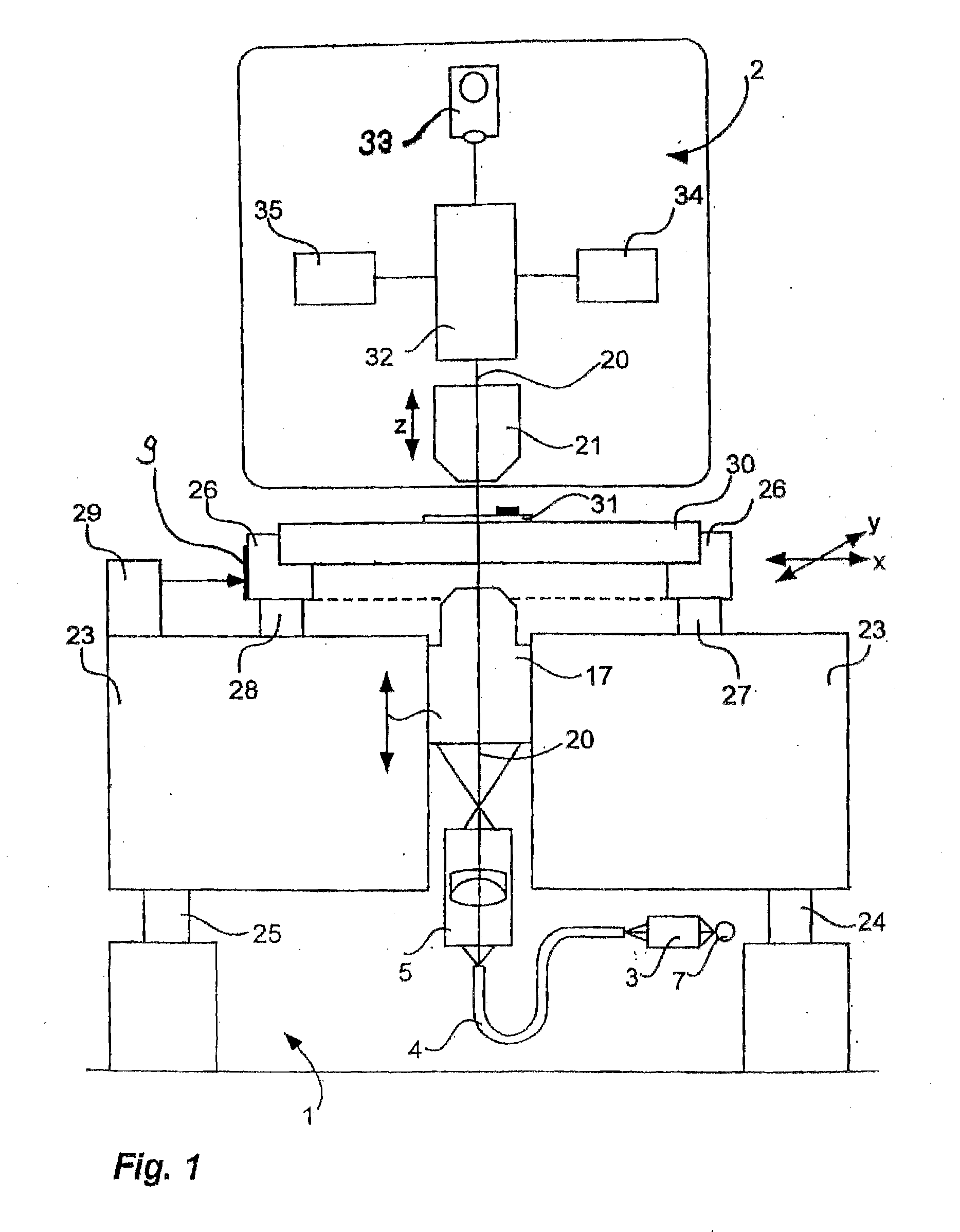
[0037] A coordinate measurement device according to FIG. 1 has already been extensively described in the introduction to the description. It is noted again that the substrate support apparatus according to the present invention can be used advantageously in such a coordinate measurement device or more generally in a position measuring device.

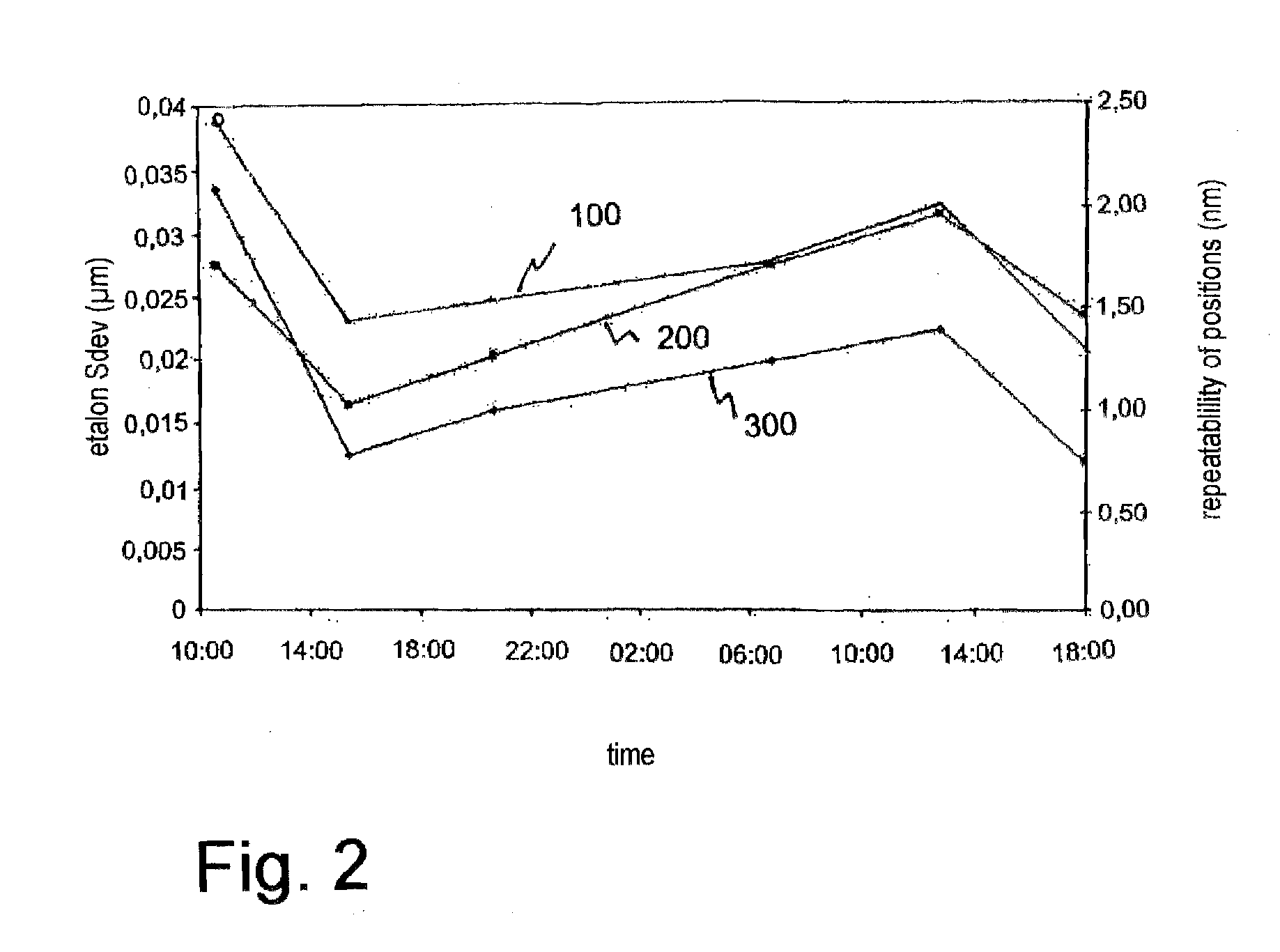
[0038] FIGS. 2 to 4 have already been discussed to explain the invention.

[0039]FIG. 5 shows an embodiment of a substrate support apparatus according to the present invention in which the measurement-critical components are made of material structures having moduli of elasticity differing from that of the substrate 45 to be investigated, here a mask, by not more than 10%. Equal components have been indicated with the same reference numerals as in FIG. 4. FIG. 5 further schematically shows the arrangement of laser interferometer system 29 and etalon 47. A laser gun 50 emits a laser beam 52 which is directed into a laser interferometer system 29 ...


PUM


Abstract

The invention relates to a substrate support apparatus ( 41 ) for use in a position measuring device ( 1 ) for determining the position of a substrate ( 30, 45 ) supported by the substrate support apparatus ( 41 ) by means of a laser interferometer system ( 29 ), wherein the substrate support apparatus ( 41 ) comprises a traversable stage construction ( 26, 42 ), and a stage mirror ( 9, 43 ) fixedly associated with the stage construction for reflecting a laser beam of the laser interferometer system, wherein it is suggested that the measurement-critical components, associated in a spatially fixed way, of the substrate support apparatus ( 41 ) in the combination of elements ranging from the stage mirror ( 9, 43 ) to the substrate ( 30, 45 ) are of material structures having moduli of elasticity which differ from that of the substrate ( 30, 45 ) by not more than 15%. As a result, the negative effects of air pressure fluctuations on the laser-interferometric position measurement can be greatly reduced.

Description

RELATED APPLICATIONS [0001] This patent application claims priority of German Patent Application No. 10 2005 052 758.2, filed on Nov. 4, 2005, which is incorporated herein by reference. FIELD OF THE INVENTION [0002] The present invention relates to a substrate support apparatus for use in a position measuring device for determining the position of a substrate supported by the substrate support apparatus by means of a laser interferometer system, wherein the substrate support apparatus comprises a traversable stage construction, and a stage mirror fixedly associated with the stage construction for reflecting a laser beam of the laser interferometer system. BACKGROUND OF THE INVENTION [0003] A measuring device for measuring structures on wafers and masks used for their manufacture has been described in detail in the convention paper entitled “Pattern Placement Metrology for Mask Making” by Dr. Carola Blasing published for the Semicon, Education Program Convention in Geneva on Mar. 31,...

Claims


Application Information

Patent Timeline
Patent Type & Authority Applications(United States)
IPC IPC(8): G03B27/58
CPCG03F7/70625G03F7/70716
Inventor FERBER, MICHAELRINN, KLAUS
Owner VISTEC SEMICON SYST
Learn More