Timing recovery phase locked loop

a phase locking loop and recovery phase technology, applied in the field of timing recovery phase locking loop, can solve the problems of loss of frequency locking condition of phase locking loop, leakage of voltage in the capacity, and high implementation cost of capacity, so as to reduce the frequency of phase locking loop control loops and reduce the frequency. the effect of frequency

Inactive Publication Date: 2007-05-10
INFINEON TECH AG
View PDF10 Cites 17 Cited by
  • Summary
  • Abstract
  • Description
  • Claims
  • Application Information

AI Technical Summary

Benefits of technology

[0020] According to another embodiment of the present invention a timing recovery phase locked loop is provided comprising a first decimator unit coupled between the first phase detector and the control unit to parallelize the first phase difference signal and to reduce its frequency and a second decimator unit coupled between the second phase detector and the control unit to parallelize the second phase difference signal and to reduce its frequency. The provision of the decimator unit has the advantage that the frequency within the control loop of the phase locked loop can be reduced which facilitates the electronic circuit design of such a digital control loop.

Problems solved by technology

This may result in the phase locked loop losing its frequency locking condition if the input data signal contains long periods of time wherein no level transition (edge) occurs.
Therefore, in an analog phase locked loop, as conventionally used, a control voltage of the voltage controlled oscillator can be held by a capacity which is, however, expensive to implement.
Further, the voltage in the capacity is subjected to leakage, whereby an unlocking of the timing recovery phase locked loop may result.

Method used


Image

  • Timing recovery phase locked loop
  • Timing recovery phase locked loop
  • Timing recovery phase locked loop

Examples


Embodiment Construction

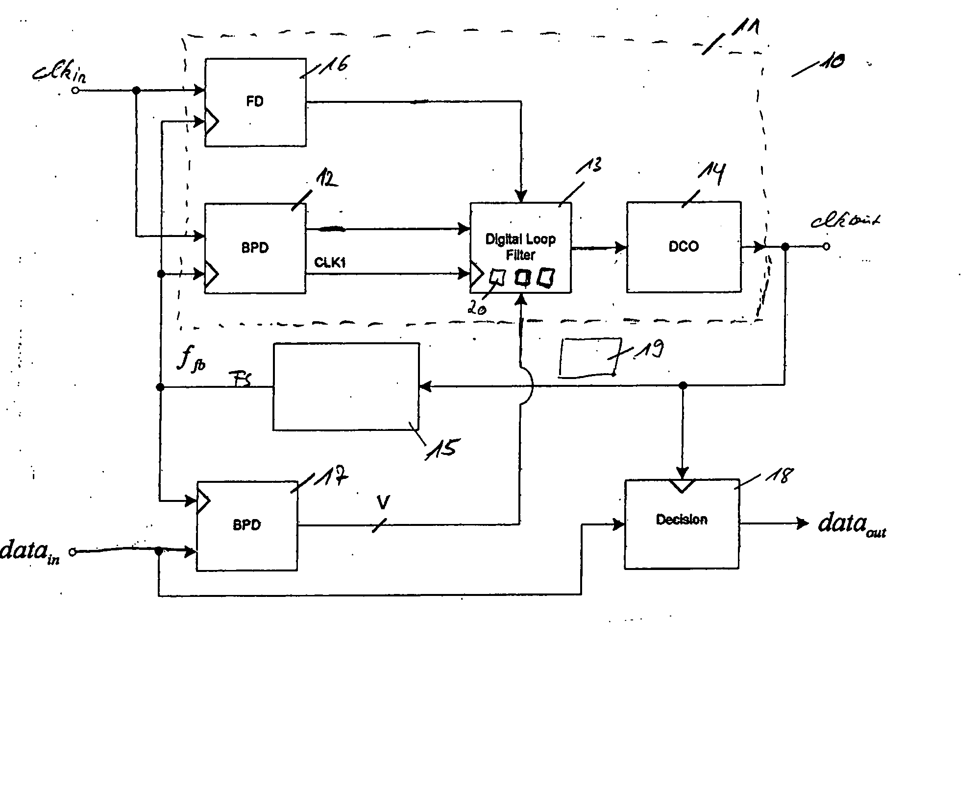
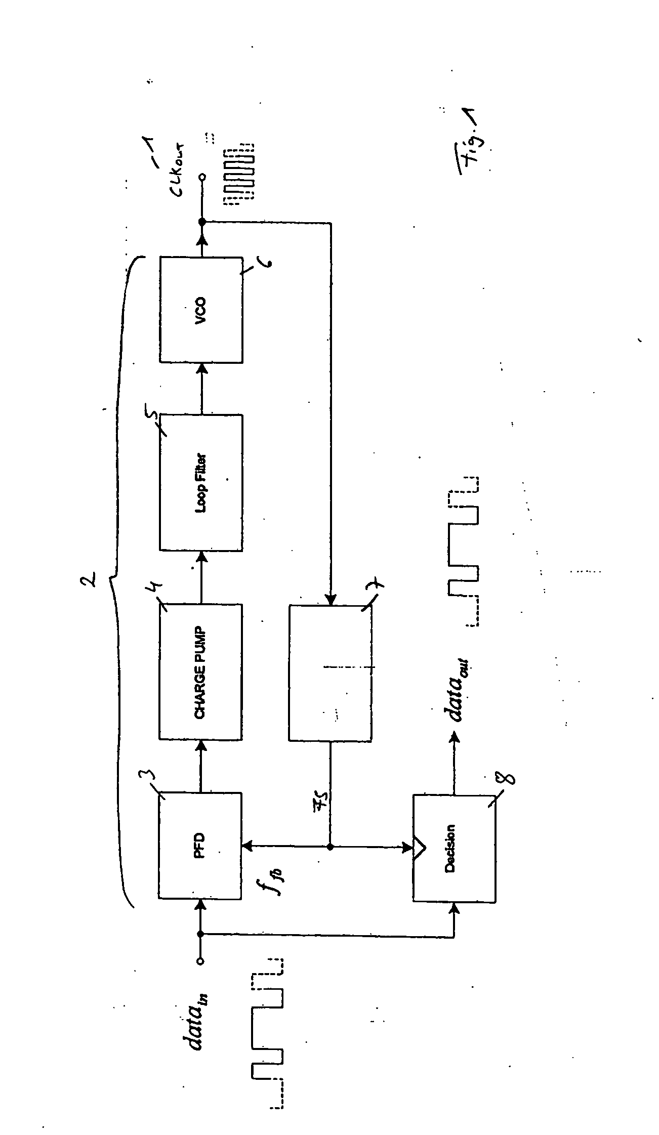
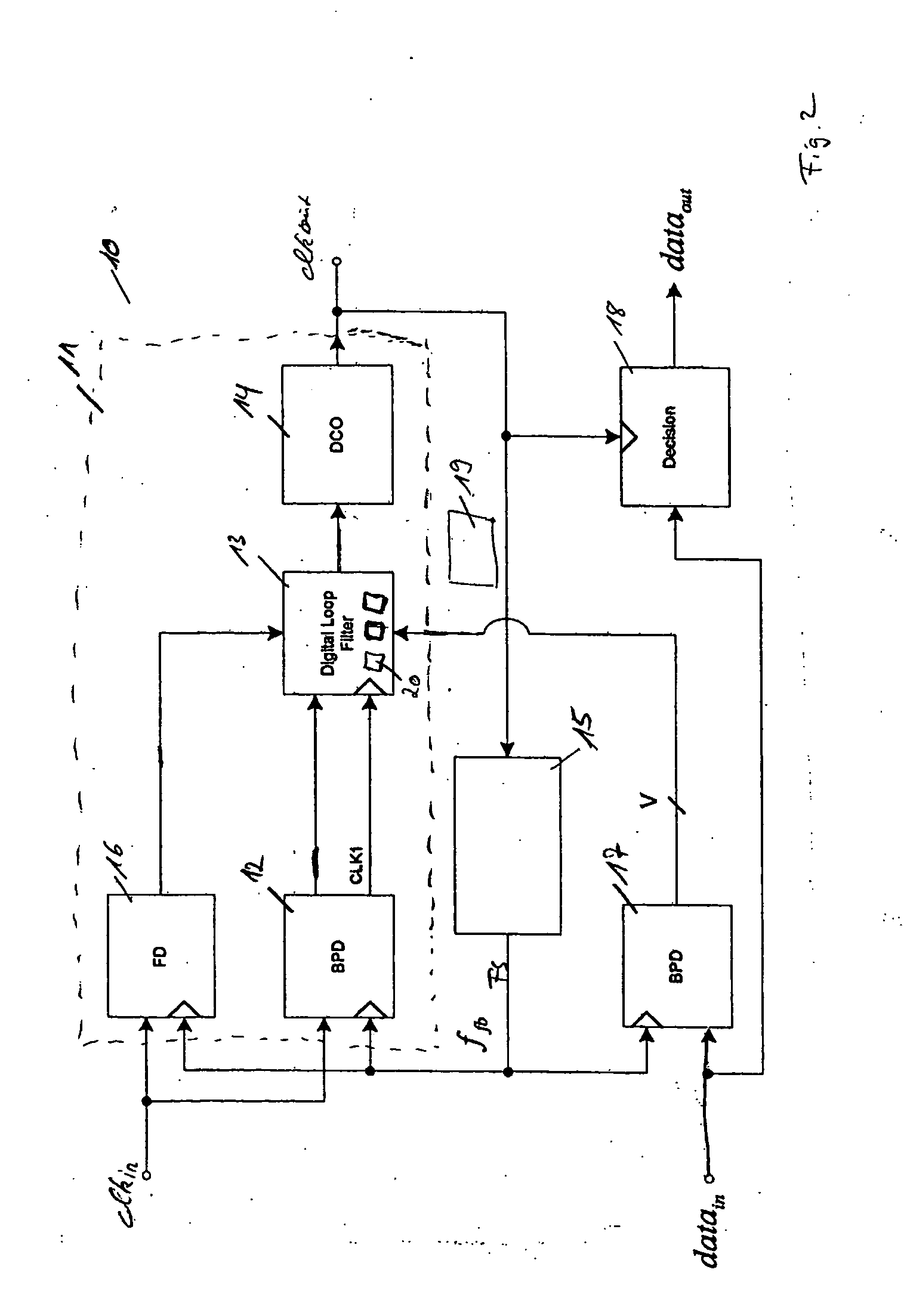
[0029]FIG. 1 shows a block diagram of a timing recovery phase locked loop 1 having one data input for receiving an input data signal DATAin to synchronize the input data signal DATAin with a generated output clock signal CLKout. The incoming data stream is substantial because no reference clock signal is provided. Therefore, a control loop 2 of the phase locked loop 1 depends on the data density of the input data signal DATAin which means that level transitions of the input data signal DATAin have to occur regularly such that the phase locked loop 1 can maintain the frequency of the clock signal the input data signal DATAin is based on. Otherwise, such a phase locked loop may unlock if the input data signal DATAin comprises a series of data bits without the occurrence of level transitions. To avoid this in conventional systems a coding of the input data signal is required. Another possibility to prevent an unlocking lies in the implementing of a hold-over mode wherein the frequency ...


PUM


Abstract

Methods and apparatus for timing recovery phase locked loops. One embodiment provides a phase detectors for generating phase difference signals on the basis of a received feedback signal and an input clock signal and an input data signal, respectively. A digital control unit is adapted to generate a control signal depending on the first and second phase difference signals A digitally controlled oscillator generates an output clock signal depending on the control signal. A feedback unit feeds the output clock signal to an input of the first phase detector as the feedback signal. And a data acquisition unit receives the data signal and the output clock signal of the digitally controlled oscillator to provide a data output signal synchronized to the output clock signal.

Description

BACKGROUND OF THE INVENTION [0001] 1. Field of the Invention [0002] The present invention relates to a timing recovery phase locked loop receiving a clock signal and a data signal wherein the data signal is sampled and latched depending on an output clock signal. [0003] 2. Description of the Related Art [0004] A timing recovery phase locked loop is designed to generate an output clock signal by which an input data signal can be sampled and / or latched. Usually no input clock signal is initially provided such that the stability of the control loop substantially depends on the data density of the input data signal, i.e. the density of rising and falling edges of the input data signal. This may result in the phase locked loop losing its frequency locking condition if the input data signal contains long periods of time wherein no level transition (edge) occurs. To prevent such an unlocking the input data signal (data stream) is typically coded—the input data signal having a restriction t...

Claims


Application Information

Patent Timeline
Patent Type & Authority Applications(United States)
IPC IPC(8): H03D3/24
CPCH03L7/087H03L7/091H03L7/0991H03L7/113H03L7/146H03L2207/50H04L7/033
Inventor GREGORIUS, PETER
Owner INFINEON TECH AG
Why Eureka
Try Eureka