Image pickup apparatus and image pickup system

a technology of image pickup and image, which is applied in the direction of camera focusing arrangement, printers, instruments, etc., can solve the problems of reducing ease of operation, unable to immediately shift from a photographable state to a photographable state, and taking a long time to obtain a photographable state, etc., to achieve enhanced ease of operation, shorten the shift time from a switch-on to a photographable state, and start quickly

Active Publication Date: 2007-05-10
PANASONIC CORP
View PDF2 Cites 28 Cited by
  • Summary
  • Abstract
  • Description
  • Claims
  • Application Information

AI Technical Summary

Benefits of technology

[0015] According to the camera apparatus and camera system of the present invention, the transmission operation of unique information or setting information from the lens unit to the camera unit at a time of start-up of the lens unit can be omitted in accordance with the state of the lens unit or the camera unit. Therefore, the lens unit can be started up quickly. Thus, in the camera unit, a shift time from switch-on to a photographable state can be shortened to enhance ease of operation.
[0016] Furthermore, in the case where a lens is started up from a state where the supply of power to the lens is stopped for power saving (a so-called sleep state of the camera unit and a power-off state of the lens unit), and photographing is performed, the start-up time of the camera system can be shortened. Therefore, there is a great effect that photographing can be performed without letting a photo opportunity slip away.
[0017] Furthermore, when the lens unit is mounted on the camera unit, the camera unit does not need to read identification information on the lens unit and can determine the configuration of a lens only based on the information of the mounting detector without performing communication. Therefore, there is a great effect that the camera system can speed up the start-up of a lens.

Problems solved by technology

However, according to the above-mentioned conventional configuration, when the lens unit is mounted on the camera unit, or when the camera unit with the lens unit mounted thereon is switched on, the camera unit performs processing of acquiring lens data from the lens unit, so that it takes a long time to obtain a photographable state from the time at which the lens unit is mounted on the camera unit or the time at which the camera unit is switched on.
This lets a shutter chance slip away, causing a decrease in ease of operation.
The transmission / reception of lens data and the settings in the camera unit as described above are performed every time the camera unit is switched on, so that there is a problem that the state cannot be shifted to a photographable state immediately after the camera system is switched on.
Furthermore, a high-performance exchangeable lens has a large amount of lens data.
When the amount of lens data is large, it takes a long time for the transmission / reception of lens data between the camera unit and the lens unit, which slows down the start-up of the camera system.

Method used


Image

  • Image pickup apparatus and image pickup system
  • Image pickup apparatus and image pickup system
  • Image pickup apparatus and image pickup system

Examples


embodiment 1

[1. Configuration of a Camera System]

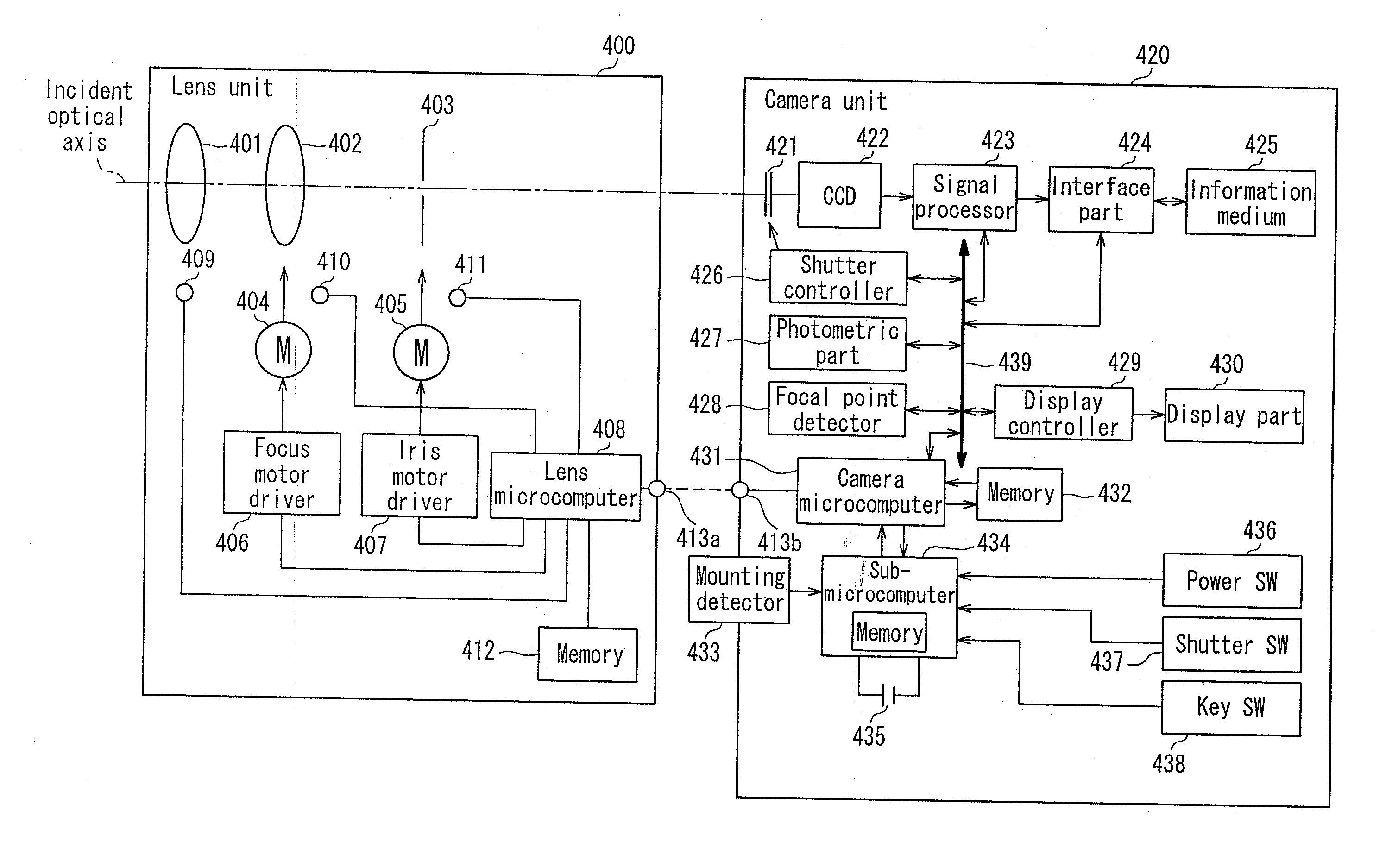
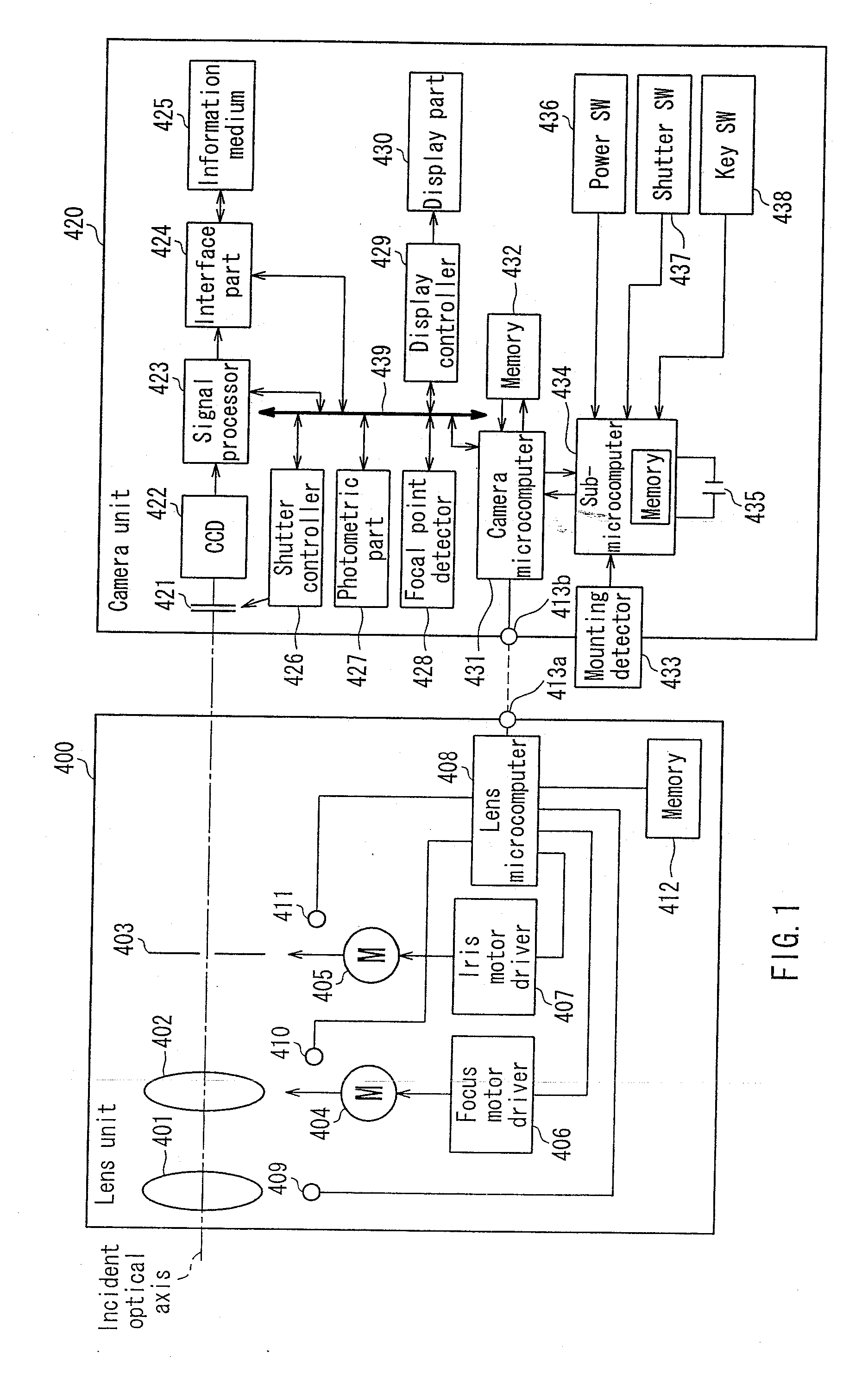
[0024]FIG. 1 is a block diagram showing a configuration of a camera system of an exchangeable lens system in the present embodiment. As shown in FIG. 1, the camera system of the present embodiment is composed of a lens unit 400 and a camera unit 420.

[0025] The lens unit 400 includes a zoom lens 401, a focus lens 402, an iris 403, a focus motor 404, an iris motor 405, a focus motor driver 406, an iris motor driver 407, a lens microcomputer 408, a zoom encoder 409, a focus encoder 410, an iris encoder 411, a memory 412, and a first communication terminal 413a.

[0026] The lens microcomputer 408 can control the driving of the focus motor 404 via the focus motor driver 406. This enables the focus motor 404 to operate the focus lens 402. Furthermore, the lens microcomputer 408 can control the driving of the iris motor 405 via the iris motor driver 407. This enables the iris motor 405 to operate the iris 403. Furthermore, the lens microcomputer 408 ari...

embodiment 2

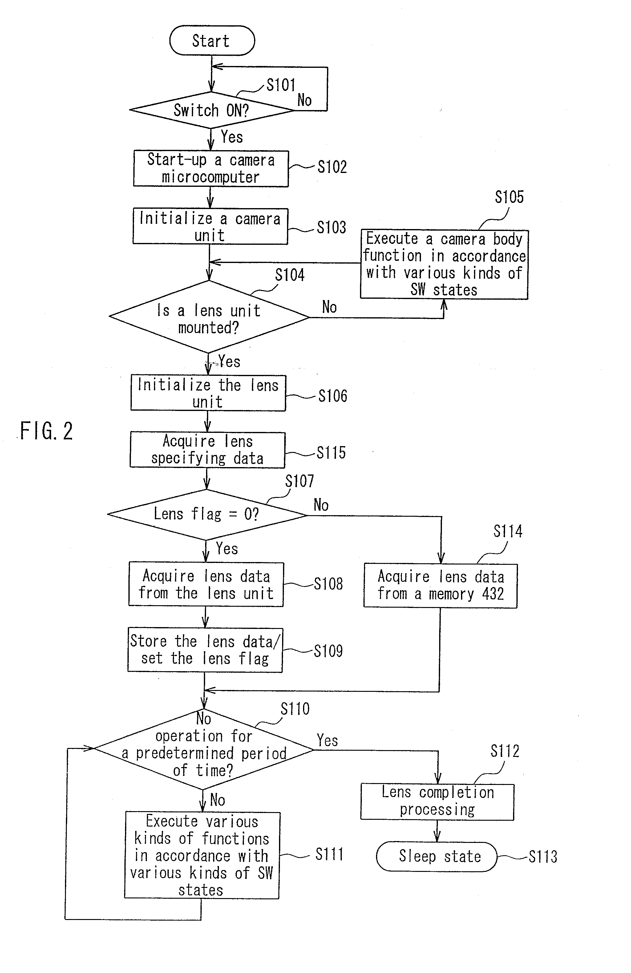
[0110]FIG. 5 is a flowchart showing an operation of a camera 5 microcomputer of embodiment 2. In FIG. 5, the same steps as those in the flowchart in FIG. 2 are denoted with the same reference numerals as those therein, and the detailed description thereof will be omitted.

[0111] Furthermore, the camera microcomputer of Embodiment 2 is operated based on the block diagram shown in FIG. 1; however, the data stored in the memories 412 and 432 are different between Embodiments 1 and 2. In the memory 412 of Embodiment 2, unique information composed of identification information (hereinafter, referred to as a “lens ID”) set for each lens and setting information (hereinafter, referred to as “lens data”) containing a focus lens position, an iris amount, and the like is written. Furthermore, in the memory 432, a plurality of pieces of unique information, composed of a lens ID varying for each type and each product no. and lens data corresponding to the lens ID, are written. The identification...

embodiment 3

[0126]FIG. 6 is a flowchart showing an operation of a camera microcomputer of Embodiment 3. In FIG. 3, the same steps as those in the flowcharts in FIGS. 2 and 5 are denoted with the same reference numerals as those therein, and the detailed description thereof will be omitted.

[0127] The camera microcomputer of Embodiment 3 is operated based on the block diagram shown in FIG. 1; however, the configuration of the memory 432 is different between Embodiments 1 and 3. The memory 432 of the camera unit 420 includes a first region capable of storing lens data (hereinafter, referred to as “first lens data”) acquired from the lens unit 400, and a second region storing unique information composed of a lens ID and lens data (hereinafter, referred to as “second lens data”) previously written at a time of shipment from a factory. In Embodiment 3, although the first lens data and the unique information are stored in one memory 432, the following configuration also may be possible: a rewritable ...


PUM


Abstract

A camera apparatus and a camera system of the present invention are configured so that a lens unit is attachable/detachable. The lens unit contains at least a lens and an iris, and contains a memory storing setting information required for operating the lens and the iris. When a camera microcomputer checks detection information stored in a memory in a sub-microcomputer at a time of start-up of the camera apparatus, and first detection information is stored in the memory, the setting information is acquired from the lens unit. When second detection information is stored in the memory, the setting information is acquired from another memory in the camera apparatus. Due to this configuration, the time for shifting the switch-on to a photographable state is shortened, and the ease of convenience can be enhanced.

Description

BACKGROUND OF THE INVENTION [0001] 1. Field of the Invention [0002] The present invention relates to a camera apparatus to which a lens unit is attachable / detachable. The present invention also relates to a camera system having a camera unit and a lens unit exchangeable with respect to the camera unit. In particular, the present invention relates to a system in which a camera unit and a lens unit can communicate with each other so that unique information of the lens unit can be communicated to the camera unit. [0003] 2. Description of Related Art [0004] Recently, in a camera system of an exchangeable lens system, respective driving systems such as focus driving means, exposure driving means, and zoom driving means are provided on a lens unit side, and control means for controlling the respective driving systems on the lens unit side is provided on a camera unit side. Furthermore, the camera system includes communication means enabling control data to be communicated between the came...

Claims


Application Information

Patent Timeline
Patent Type & Authority Applications(United States)
IPC IPC(8): G03B3/00
CPCG03B17/14G03B17/18H04N5/23209H04N23/663
Inventor TAMURA, AKIHIRO
Owner PANASONIC CORP
Why Eureka
Try Eureka