Implantable electrophysiology lead body
a lead body and electrophysiology technology, applied in the field of medical electrical lead bodies, can solve the problems of vivo) mechanical damage to the body made of the material, cases of acute allergic reactions in some patients,
- Summary
- Abstract
- Description
- Claims
- Application Information
AI Technical Summary
Benefits of technology
Problems solved by technology
Method used
Image
Examples
example 1
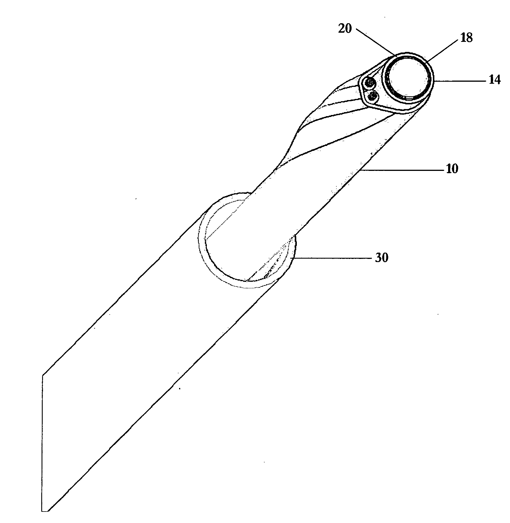
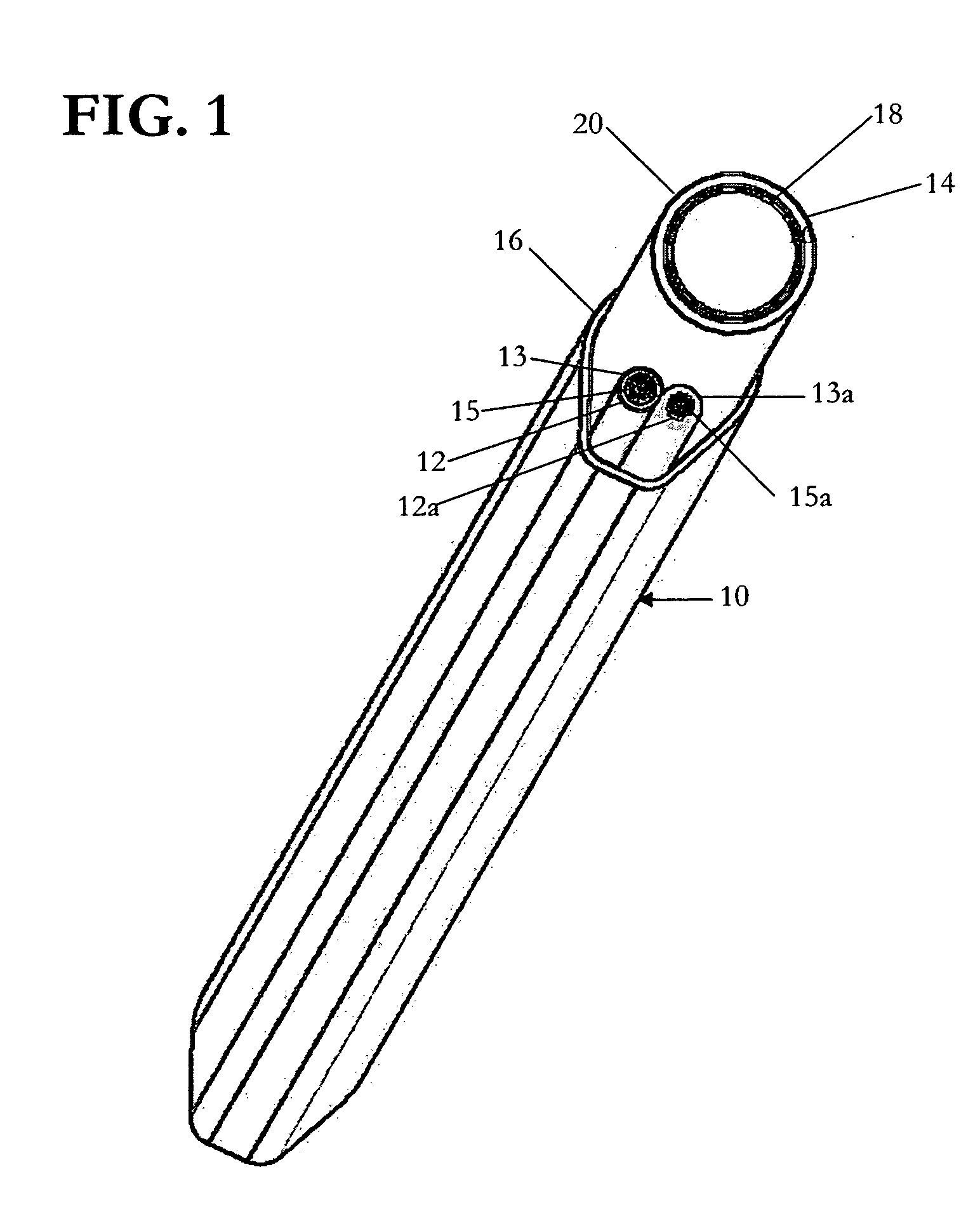
[0049] An all-fluoropolymer lead body suitable for cardiac implantation as shown in FIG. 1 was constructed in the following manner:
[0050] A thin-walled fluoropolymer composite lumen 14 was first constructed. The lumen in this example comprised a fluoropolymer laminate having an inner layer (18) of nonporous ePTFE and an outer layer (20) of porous ePTFE. Non-porous ePTFE film of thickness equal to about 0.0005 inches, which was provided with a non-porous coating of FEP on one side, was cut into tape 0.185 inches wide. The non-porous ePTFE film has a bulk density of about 2.1 g / cc. After cutting the coated film into a tape, the tape was wrapped on a 0.040 inch diameter silver plated copper mandrel in an overlapping fashion with the FEP coated side of the tape facing away from the mandrel. The tape was wrapped at a pitch of about 20 degrees and overlapped about 25 percent. During wrapping, the tape was tensioned at 600 grams.
[0051] Porous ePTFE tape was wrapped around the non-porous ...
example 2
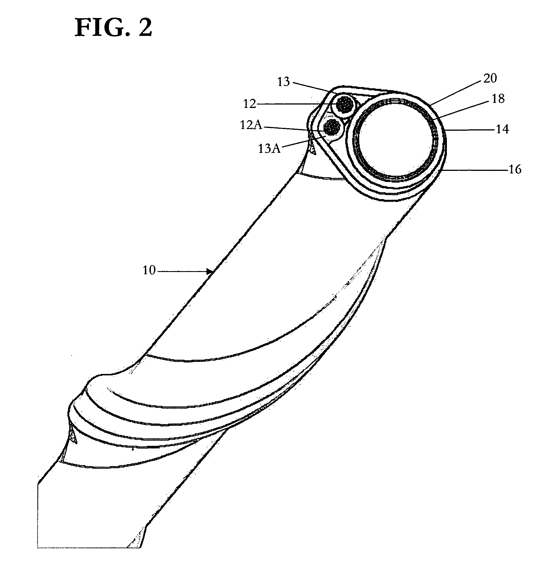
[0056] A second lead body, constructed using techniques similar to those of Example 1. However, this lead body is smaller and may be suitable for use in neurologic applications. As in Example 1, the lead body comprises two insulated conductors (12, 12a), but in this example, depicted in FIG. 2, the conductors are helically wrapped around a fluoropolymer lumen (14). These longitudinal elements are then covered with a fluoropolymer tape wrapping (16).
[0057] A 0.020 inch inner diameter lumen (14) was constructed by wrapping a silver plated copper mandrel with porous and non-porous fluoropolymer tape to construct a composite fluoropolymer tube. The lumen had an inner layer of non-porous ePTFE tape and an outer layer of porous ePTFE tape. The two-layer construction had a total wall thickness equal to 0.001 inches. First, a 0.0005 inch thick, 0.050 inch wide, non-porous ePTFE tape was wrapped at an angle of approximately 20 degrees around the mandrel at a tension of 175 grams with a 25 p...
example 3
[0060] An elastic lead body can be constructed by using porous ePTFE tape in which at least some of the porosity is filled with an elastomer such as silicone or urethane. As used herein, an elastic lead body means a lead body that will deform at least 3% in the direction of an applied load and return to its un-deformed state upon removal of such load. Methods of preparing filled or imbibed ePTFE films are taught in U.S. Pat. No. 6,673,455, and U.S. Pat. No. 6,451,396, to Zumbrum et. al and are incorporated herein by reference.
[0061] A thin-walled lumen was first constructed. The lumen comprised a fluoropolymer laminate having layers of porous ePTFE imbibed with silicone. Porous ePTFE film of thickness equal to about 0.001 inches was cut into a 0.2 inches wide tape. The tape was then wrapped on a 0.016 inch diameter silver plated copper mandrel in an overlapping fashion. The tape was wrapped at a pitch of about 25 degrees and overlapped about 75 percent. During wrapping, the tape wa...
PUM
 Abstract
Description
Claims
Application Information
 - R&D
- Intellectual Property
- Life Sciences
- Materials
- Tech Scout
- Unparalleled Data Quality
- Higher Quality Content
- 60% Fewer Hallucinations
Browse by: Latest US Patents, China's latest patents, Technical Efficacy Thesaurus, Application Domain, Technology Topic, Popular Technical Reports.
© 2025 PatSnap. All rights reserved.Legal|Privacy policy|Modern Slavery Act Transparency Statement|Sitemap|About US| Contact US: help@patsnap.com


