Intravascular Electronics Carrier Electrode for a Transvascular Tissue Stimulation System

a tissue stimulation system and transvascular technology, applied in electrotherapy, heart stimulators, therapy, etc., can solve the problems of limited flexibility of the electrode/carrier assembly, potential apparatus failure,

Inactive Publication Date: 2007-05-10
KENERGY INC
View PDF15 Cites 111 Cited by
  • Summary
  • Abstract
  • Description
  • Claims
  • Application Information

AI Technical Summary

Benefits of technology

[0010] In an implanted medical device for stimulation of body tissue, a material and mechanical transition between an electrical lead and an electrode carrier is avoided by incorporating the conductor of the lead into the carrier.

Problems solved by technology

A challenge in designing an intravascular electronics-electrode carrier is to provide a means for reliably connecting an electrode to a carrier, such as a stent.
This type of transition provided a point of potential failure of the apparatus due to mechanical fatigue and posed a limitation on the flexibility of the electrode / carrier assembly.

Method used


Image

  • Intravascular Electronics Carrier Electrode for a Transvascular Tissue Stimulation System
  • Intravascular Electronics Carrier Electrode for a Transvascular Tissue Stimulation System
  • Intravascular Electronics Carrier Electrode for a Transvascular Tissue Stimulation System

Examples


first embodiment

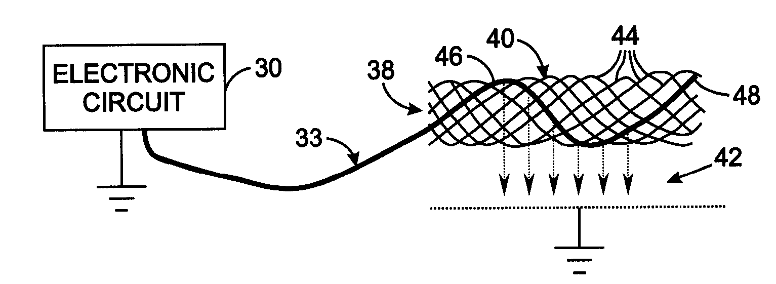
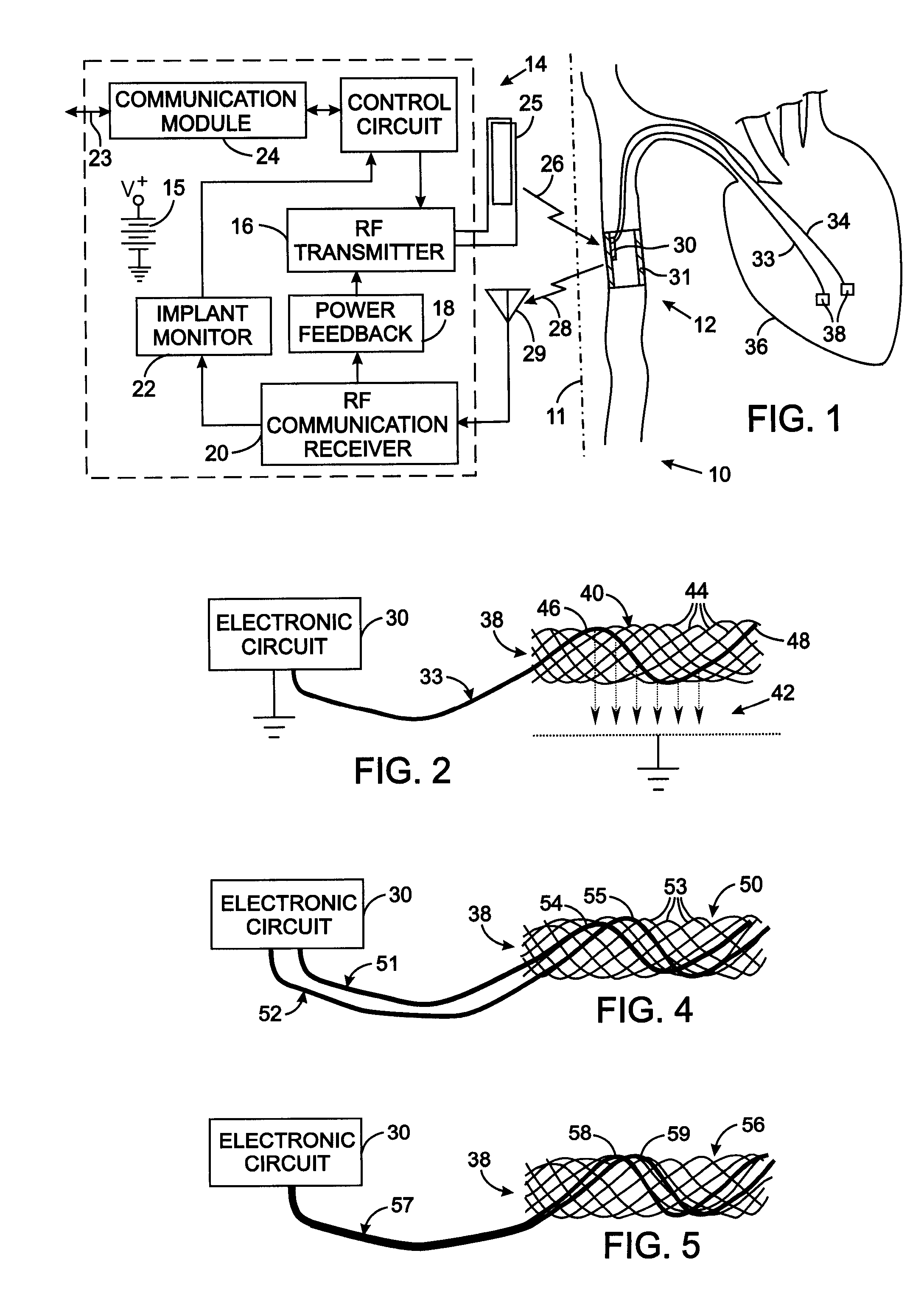
[0028]FIG. 2 illustrates the details of the electrode assembly 38 comprising an electrode carrier 40 to which an electrode lead 33 from the electronic circuit 30 connects. A mesh-type electrode carrier 40 can be employed which is similar to stents commonly used to enlarge constricted blood vessels. That type of carrier comprises a plurality of wires formed to have a memory defining a tubular shape or envelope. Those wires may be heat-treated platinum, Nitinol, a Nitinol alloy wire, stainless steel, plastic wires or other materials. Plastic or substantially nonmetallic wires may be loaded with a radiopaque substance which provides visibility with conventional fluoroscopy. A catheter assembly is used to implant the components of the medical device 12 in the animal's circulatory system. The electrode carrier 40 has a shape memory so that it normally assumes an expanded tubular configuration when unconfined, but is capable of assuming a collapsed configuration when disposed and confined...

second embodiment

[0032] In the electrode assembly 38 shown in FIG. 4, a pair of electrode leads 51 and 52 extend from the stimulator electronic circuit 30 to an electrode carrier 50 that has the same structure as electrode carrier 40 previously described. However, the stands 53 of the electrode carrier 50 do not have electrically conductive surfaces, i.e. the strands either are formed of non-conductive material or have a non-conductive surface coating. Bare conductors 54 and 55 portions of the two electrode leads 51 and 52, respectively, are interwoven into the stands of the electrode carrier 50. The bare conductors 54 and 55 are arranged so that they do not contact each other. Alternatively, only a small section of each electrode leads 51 and 52 in the electrode carrier 50 have an exposed conductor with those portions being spaced apart longitudinally along the electrode carrier 50. An electrical circuit is completed between the bare conductors 54 and 55 by the adjacent animal tissue, thereby provi...

third embodiment

[0033] With reference to FIG. 5, the electrode assembly 38 comprises an mesh-type electrode carrier 56 that has electrically non-conducting exterior surfaces similar the electrode carrier 50. A single electrode lead 57 extends from the stimulator electronic circuit 30 and has two electrically insulated conductors 58 and 59 encased in an insulating outer sheath. The two electrically insulated conductors 58 and 59 emerge from the outer sheath at the electrode carrier 50 and have their individual outer insulations removed from portions that are woven through the mesh of the electrode carrier 56. The exposed portions of each conductor are electrically separated from each other.

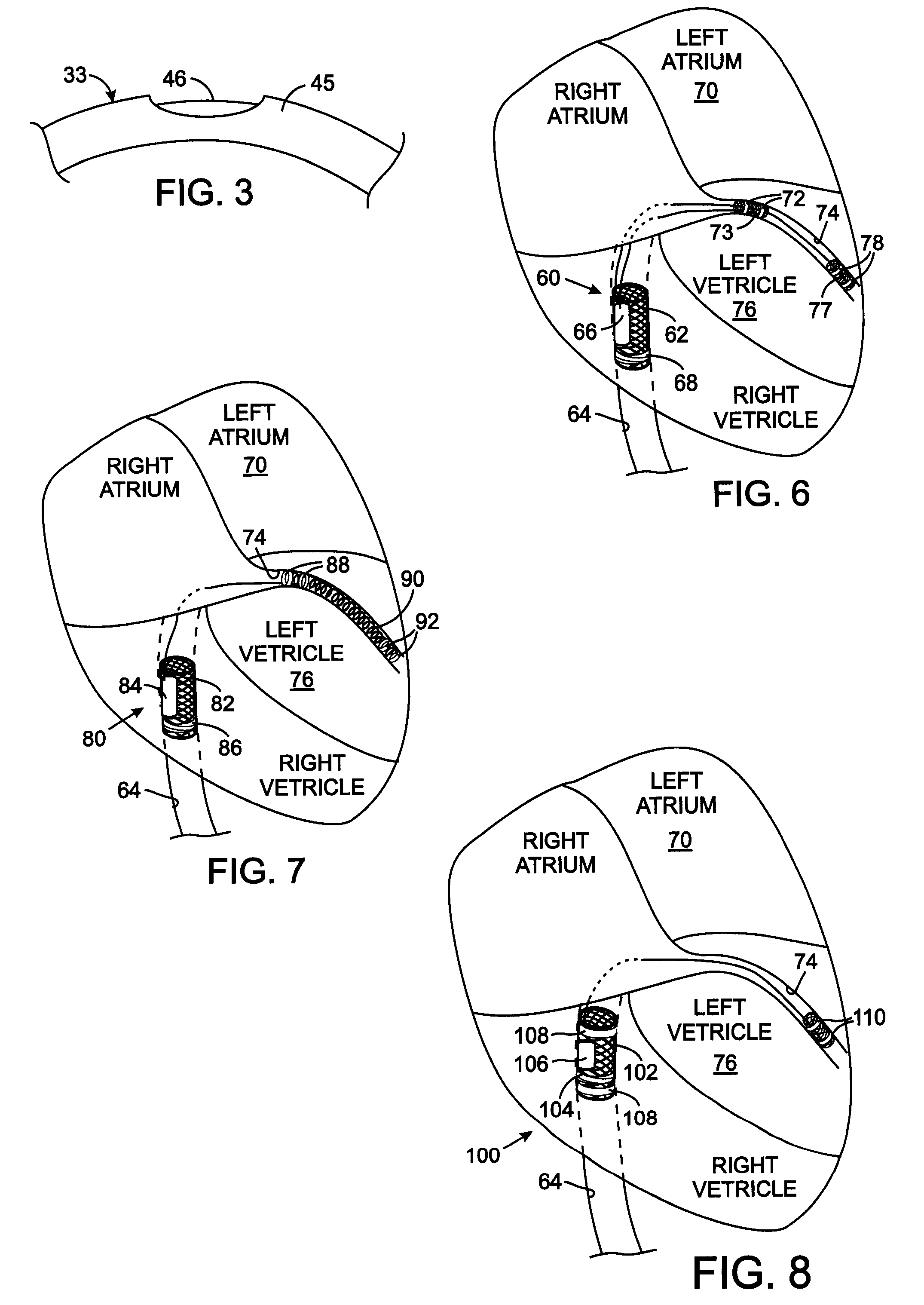
[0034] The design of a medical device that provides a reliable connection of an electrode to the conductor of the lead and to the electrode carrier requires configurations that are customized to the specific application of that device in the animal's body. FIGS. 6-8 show three exemplary configurations for such spe...


PUM


Abstract

An intravascular mesh type electrode carrier eliminates material and mechanical transitions between an electrical lead and an electrode by interweaving the conductor of the lead into the carrier mesh. The mesh material of the electrode carrier can be electrically conductive so that the entire carrier functions as the electrode. Alternatively, the mesh material may either be non-conductive or have an outer non-conductive coating, in which cases only the exposed section of the first conductor acts as an electrode. With a non-conductive mesh material, a second electrode lead can be woven through the mesh of the electrode carrier to provide a second electrode.

Description

CROSS-REFERENCE TO RELATED APPLICATIONS [0001] This application claims benefit of U.S. Provisional Patent Application No. 60 / 734,019 filed Nov. 4, 2005.STATEMENT REGARDING FEDERALLY SPONSORED RESEARCH OR DEVELOPMENT [0002] Not Applicable BACKGROUND OF THE INVENTION [0003] 1. Field of the Invention [0004] The present invention relates implantable electronic medical devices, such as cardiac pacemakers and defibrillators for example, for stimulating tissue of animal for therapeutic purposes; and more particularly to electrode assemblies for such devices. [0005] 2. Description of the Related Art [0006] A remedy for a patient with certain physiological ailments is to implant a stimulation device that applies an electrical pulse to an organ or part of an organ which is affiliated with the ailment. The stimulation device includes an electronic pulse generator from which electrical leads extend to electrodes in contact with parts of the organ, which when electrically stimulated provide ther...

Claims


Application Information

Patent Timeline
Patent Type & Authority Applications(United States)
IPC IPC(8): A61N1/00
CPCA61N1/362A61N1/372A61N1/37205A61N1/375A61N1/37512A61N1/37516
Inventor DENKER, STEPHENBEUTLER, ARTHUR J.BULKES, CHERIK
Owner KENERGY INC
Why Eureka
Try Eureka