Switching unit having a locking function for a tool

a technology of locking function and switch unit, which is applied in the field of switch unit, can solve the problems of bringing the unit to a standstill, reducing the mtbf (mean time between failures) of the unit, and reducing the life of this type of actuating element, so as to achieve the effect of not prone to wear, reducing stray flux, and being very robus

Inactive Publication Date: 2007-05-17
BOSCH REXROTH AG
View PDF6 Cites 6 Cited by
  • Summary
  • Abstract
  • Description
  • Claims
  • Application Information

AI Technical Summary

Benefits of technology

[0004] Thus, the present invention is based on the object of making available an improved switch unit having combined switch function and locking function for controlling industrial tools, and at the same time, of avoiding the disadvantages of the usual design approaches.
[0005] According to the present invention, these objects are attained by the switch unit. The switch unit having a combined switch function and locking function for controlling industrial tools has both a locking function and a switch function, both functions taking place on a magnetic basis. The switch unit is made up of two opposite rows of magnets, and each row is made up of at least two magnets. The distance between the enveloping magnet rows lying on opposite sides is essentially constant, the rows being relatively movable with respect to one another in the direction of the extension of the rows. Furthermore, the distance between the adjacent magnets of one row is essentially constant, and in one of the rows of magnets at least one magnetic field detector is provided. Consequently, the switch unit is almost free from wear, its properties are not time dependent, and the maintenance intervals provided for it are only dependent on the support of the rotary knob. Therefore, the switch unit is very robust.
[0006] In one row of magnets a magnetic field detector is provided, the detector replacing one magnet of a series and having two adjacent magnets. Moreover, the distance between the detector and each of the two magnets is approximately equivalent to the distance, or a multiple of the distance, between the magnets mounted in the opposite row. The magnets adj

Problems solved by technology

An electrical or mechanical fault in such a small part can bring the unit to a standstill.
The service life of this type of actuating el

Method used


Image

  • Switching unit having a locking function for a tool
  • Switching unit having a locking function for a tool
  • Switching unit having a locking function for a tool

Examples


Embodiment Construction

[0013] Similar or similarly functioning components are characterized in the figures by the same reference numerals, to a great extent.

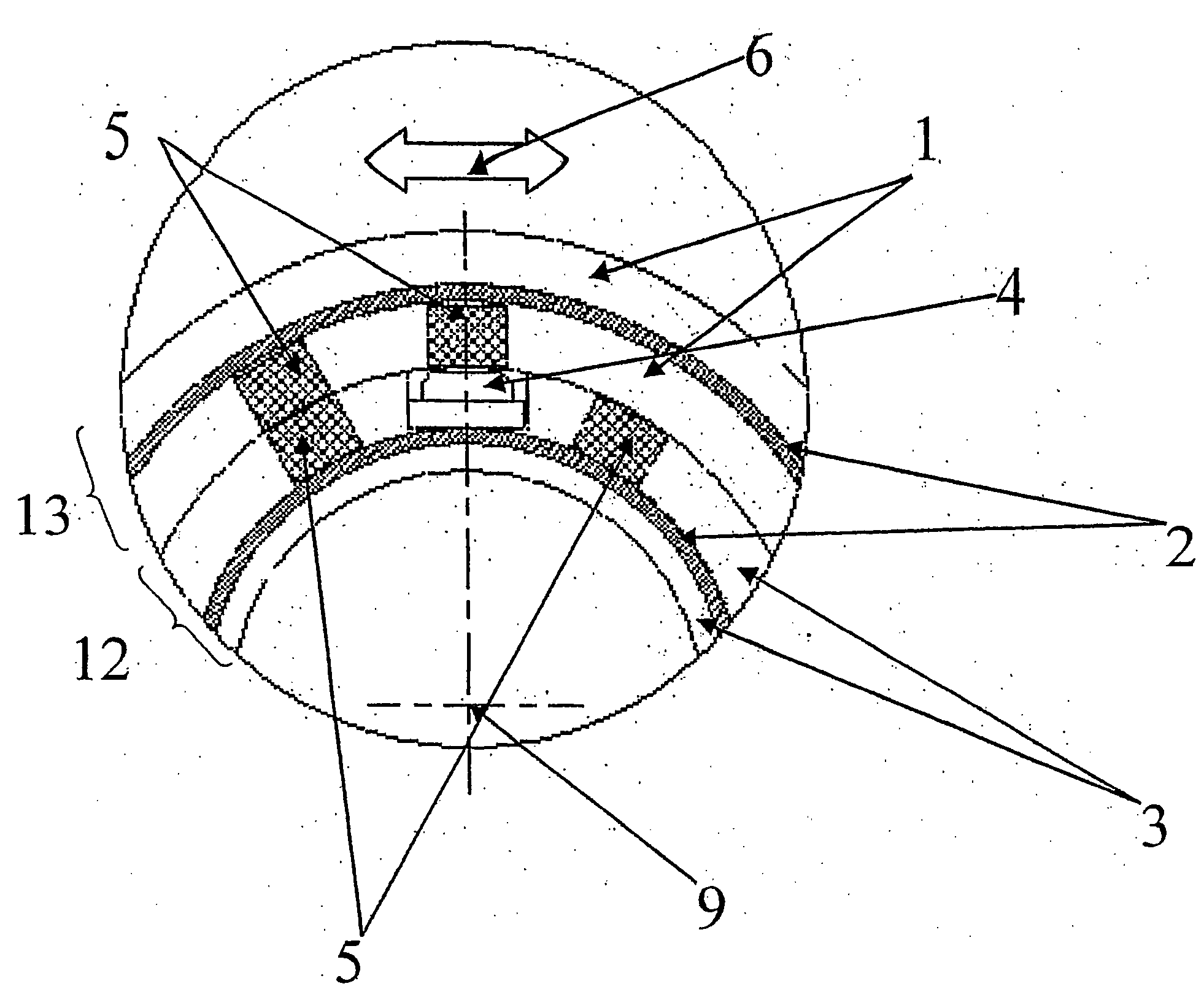
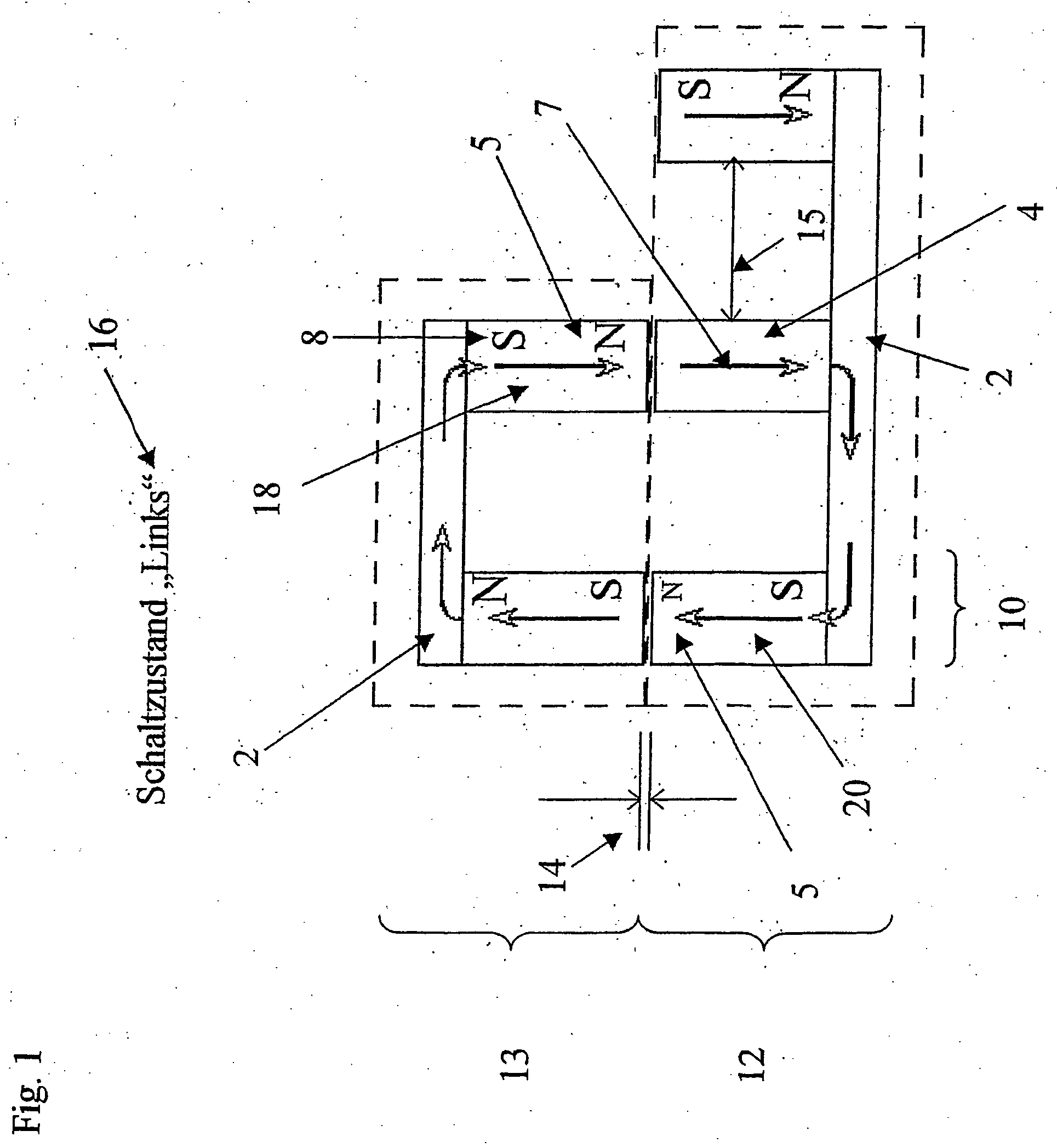
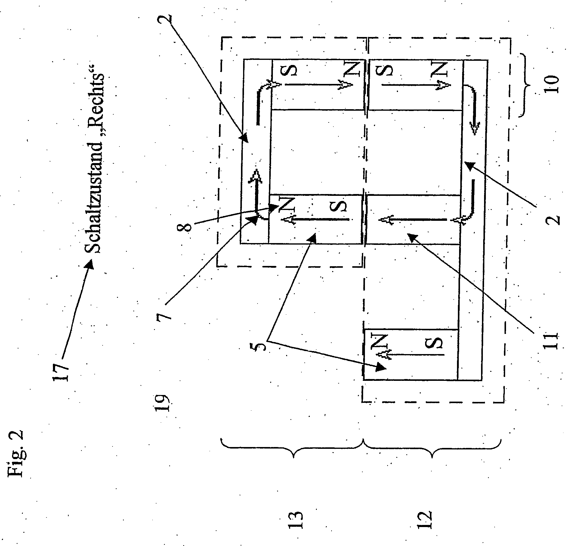
[0014]FIGS. 1, 2 and 3 show schematic representations of preferred forms of the present invention. FIGS. 1 and 2 show a magnetic circuit including two rows of magnets 12, 13, two ferromagnetic steel rings 2 assigned to the magnets, and a detector 4, 11. According to the present invention, the row of magnets 13 is relatively movable with respect to row 12, that is, row 12 is mounted in a fixed manner, whereas row 13 is able to be shifted in a left or right direction. The distance between the row 14 is also mechanically fixed, according to the present invention. However, the type and method of fixing is not shown in schematic FIGS. 1 and 2, and depends on the specific embodiment of the switch unit.

[0015] According to the present invention, detector 4, 11 always has to have a magnet 18 lying opposite to it, This results in the circuit only being able t...


PUM


Abstract

A switch unit having a combined switch function and locking function for controlling industrial tools, both the locking function and the switch function being achieved magnetically.

Description

FIELD OF THE INVENTION [0001] The present invention relates to a switch unit having a combined switching and locking function for controlling industrial tools, especially hand-held units, such as screwdrivers and drills. BACKGROUND INFORMATION [0002] Requirements on the performance of industrial tools are becoming ever greater, and the ratio of cost to benefit is especially being observed ever more critically. In all industries, the overall costs of production units are considered, and not only the acquisition price: the maintenance effort, replacement parts cost, failure rate, etc., in sum determine the service life costs of the unit. Naturally, productivity also plays a major role. Units that people like to use and that are easy to operate contribute to an increased productivity. For this reason, the user friendliness of a unit is an important differentiating feature for the suppliers of industrial tools. The actuating elements of a device are of greater meaning because they are o...

Claims


Application Information

Patent Timeline
IPC IPC(8): H01R39/00G01B7/30H01H5/02H03K17/97
CPCH01H5/02H01H2003/506H03K17/97H03K2017/9713
Inventor WIELER, MICHAELKURZ, JURGENSCHNEIDER, JORG
Owner BOSCH REXROTH AG
Why Eureka
Try Eureka