Light-emitting diode with UV-blocking nano-particles

a technology of light-emitting diodes and nano-particles, which is applied in the direction of solid-state devices, basic electric elements, electric devices, etc., can solve the problems of reduced light extraction from led chips, undesired alteration of device light emitted, and degradation of encapsulants

Inactive Publication Date: 2007-05-17
AVAGO TECH ECBU IP (SINGAPORE) PTE LTD
View PDF10 Cites 32 Cited by
  • Summary
  • Abstract
  • Description
  • Claims
  • Application Information

AI Technical Summary

Problems solved by technology

Such devices typically do not include dispersant, and emit visible light.
However, ultra-violet (“UV”) light from sunshine is absorbed by conventional polymeric encapsulant, causing degradation of the encapsulant (typically yellowing and clouding) and reduced light extraction from the...

Method used


Image

  • Light-emitting diode with UV-blocking nano-particles
  • Light-emitting diode with UV-blocking nano-particles

Examples


Embodiment Construction

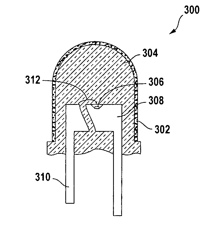
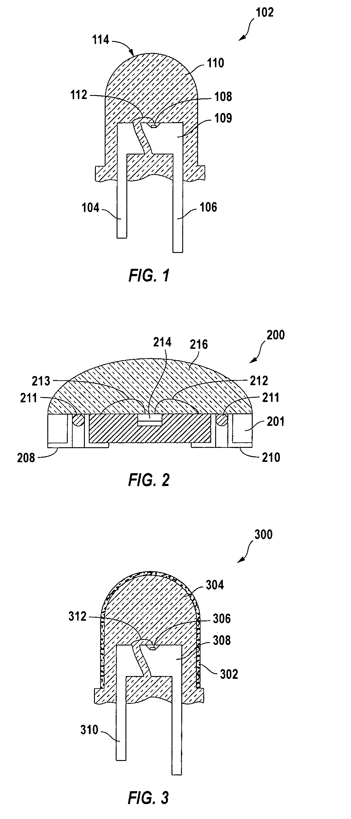
[0011]FIG. 1 shows an LED lamp 102 according to an embodiment of the invention. Leads 104, 106 have been cut from a lead frame, as is well known in the art of LED manufacturing. One lead 104 has been cut shorter than the other lead 106 to indicate the electrical polarity of the LED chip 108. One lead 106 includes a header 109 on which the LED chip 108 is mounted, frequently in a reflective cup. Encapsulant 110 secures one lead relative to the other to prevent avoid damage to the bond wire 112.

[0012] The encapsulant is made from transparent polymer, such as epoxy, silicone, polymethylmethacrylate (PMMA”), or a combination of polymers, such as a silicone-epoxy hybrid system, or other plastic(s) and is cast or molded around the LED chip. The encapsulant 110 is often shaped to form a lens 114 that facilitates a desired pattern of light extracted from the LED chip 108. In particular, the LED chip 108 produces an essentially point-source of light, and the lens 114 makes the LED lamp 102 ...


PUM


Abstract

A light-emitting device has an encapsulated light-emitter. Nano-particles substantially transparent to visible light block UV light.

Description

CROSS-REFERENCE TO RELATED APPLICATIONS [0001] Not applicable. STATEMENT REGARDING FEDERALLY SPONSORED RESEARCH OR DEVELOPMENT [0002] Not applicable. REFERENCE TO MICROFICHE APPENDIX [0003] Not applicable. BACKGROUND OF THE INVENTION [0004] Packaged light-emitting diodes (“LEDs” or “LED lamps”) typically have encapsulant dispensed onto or molded around an LED chip mounted on a header and electrically connected to leads with one or more wire bonds. The encapsulant is usually a transparent polymer, such as an epoxy or silicone, that protects the LED chip and wire bond from mechanical and environmental damage while allowing light emitted by the LED chip to pass through with minimal loss. A dispersant is sometimes added to the encapsulant to promote diffusion of the light if the light is to be used in an instrument panel. [0005] Some LEDs are intended to be used outdoors, such as in outdoor signage. Such devices typically do not include dispersant, and emit visible light. However, ultra...

Claims


Application Information

Patent Timeline
IPC IPC(8): H01L33/00H01L33/44H01L33/56
CPCH01L33/44H01L33/56H01L2924/181H01L2224/48091H01L2224/48247H01L2924/00012H01L2924/00014
Inventor CHUA, JANET BEE YINLAU, YUE HOONG
Owner AVAGO TECH ECBU IP (SINGAPORE) PTE LTD
Why Eureka
Try Eureka