
Rechargeable battery pack for a power tool

Inactive Publication Date: 2007-05-17
MATSUSHITA ELECTRIC WORKS LTD
View PDF8 Cites 55 Cited by
  • Summary
  • Abstract
  • Description
  • Claims
  • Application Information

AI Technical Summary

Benefits of technology

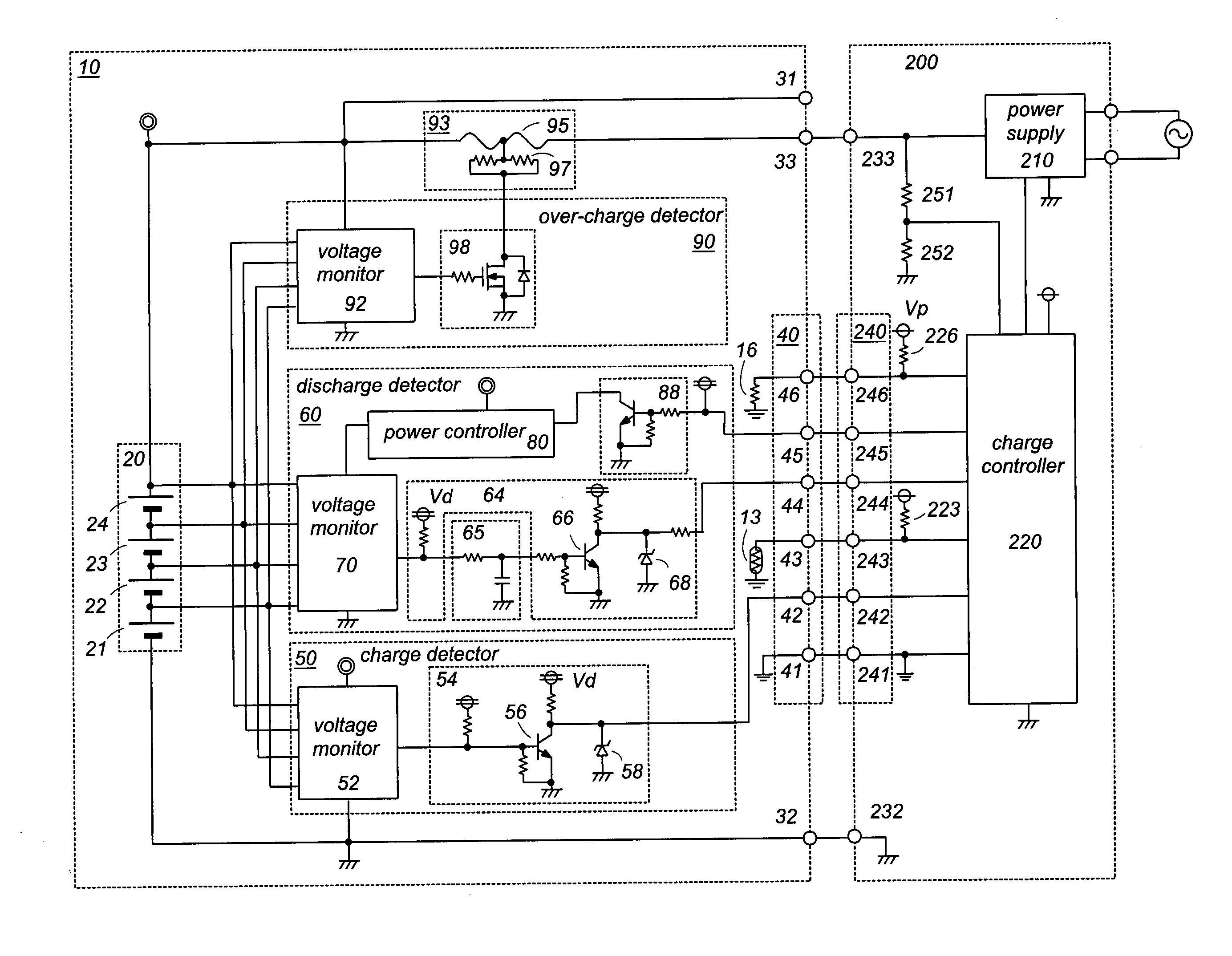
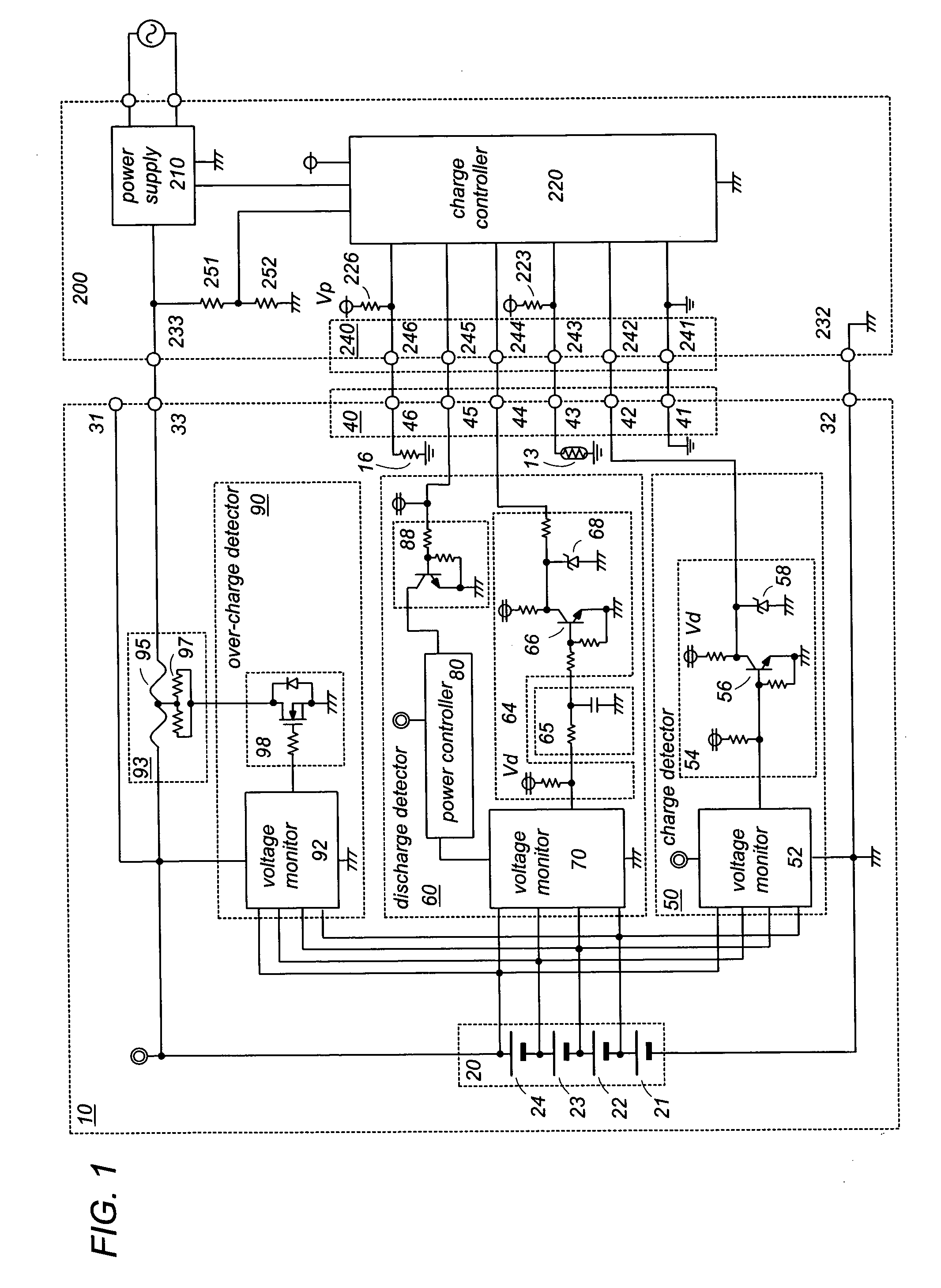
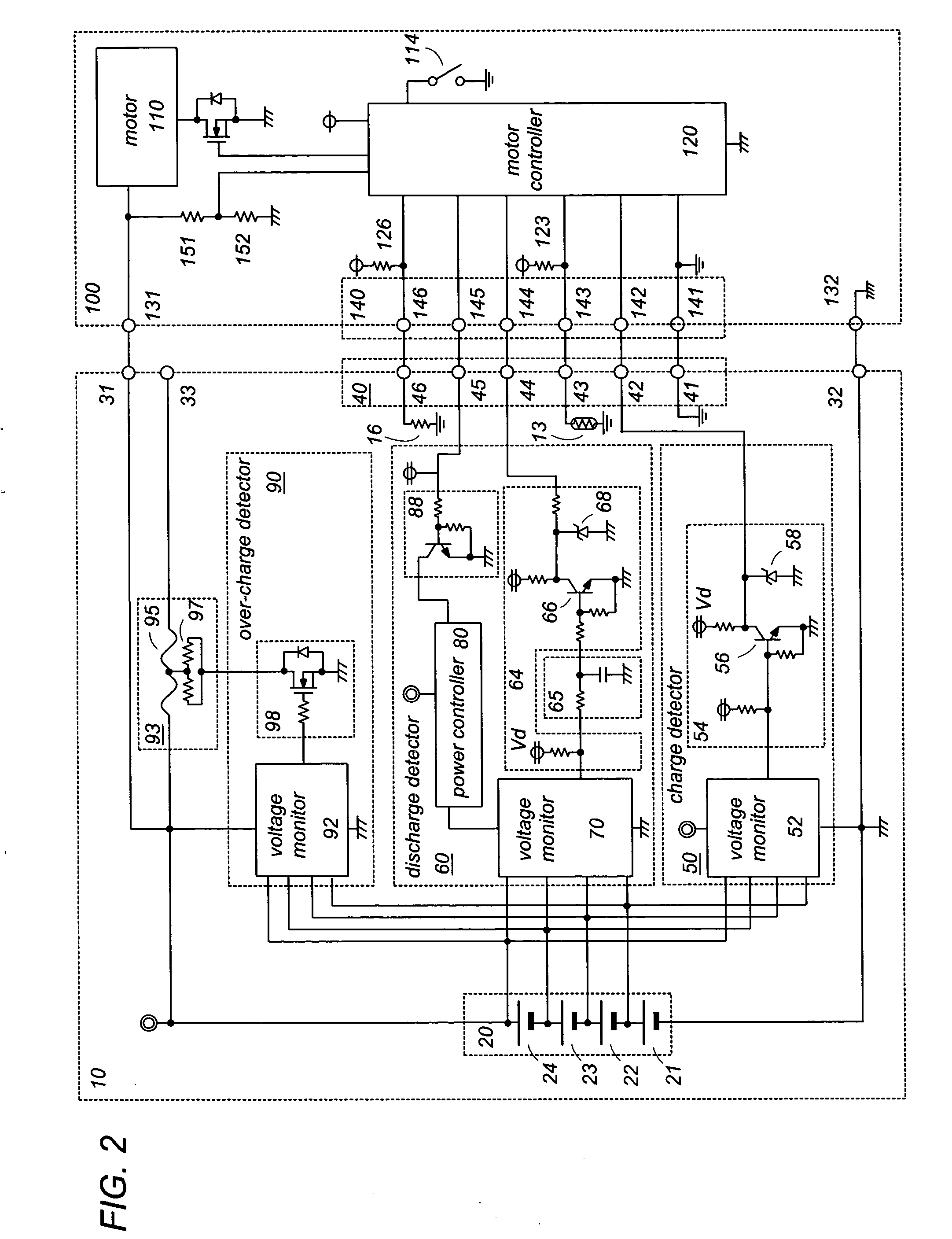
[0004] In view of the above problem, the present invention has been accomplished to provide a rechargeable battery pack for a power tool which is capable of avoiding an over-discharging when connected to operate the power tool, yet being protected from being exhausted while it is left disconnected from a charger. The battery pack in accordance with the present invention includes a battery stack composed of a plurality of series connected secondary cells, a pair of power output terminals connected across the battery stack to supply a voltage of the battery stack for operating the power tool, and a signal connector configured to include a charge control terminal, a discharge control terminal, and a signal ground terminal connected to a circuit ground. The battery pack includes a charge detector which is configured to monitor a cell voltage appearing across each of the secondary cells and to provide a high charge-control signal when all of the cell voltages are lower than a first threshold (VTH1) and a low charge-control signal when anyone of the cell voltage becomes higher than the first threshold (VTH1). The high charge-control signal and the low charge-control signal are fed through the charge control terminal to a battery charger for regulating a charge current of charging the secondary cells. The battery pack also includes a discharge detector which is configured to monitor the cell voltage across each of the secondary cells and to provide a discharge stop signal when any one of the cell voltages becomes lower than a second threshold (VTH2) which is lower than said first threshold (VTH1). The discharge stop signal is fed through the discharge control terminal to the power tool for deenergizing the power tool. The discharge controller comprises a voltage monitor and a power controller. The voltage monitor is configured to include a plurality of comparators and a plurality of constant voltage elements each providing a constant voltage that defines the second threshold (VTH2). Each of the comparators is configured to compare each of the cell voltages with the second threshold to give a comparison result. The voltage monitor is configured to be energized by the battery stack and to provide the discharge stop signal to the charge control signal based upon the comparison results. The power controller is configured to energize the voltage monitor upon the battery pack being connected to the power tool. Accordingly, the discharge detector is protected from consuming the energy of the battery pack while being disconnected from the power tool, thereby assuring to give a long battery life while retaining an advantage of protecting the battery pack from being over-discharged during the use of the power tool.
[0005] Preferably, the power controller is configured to have a plurality of different current supply paths which supply a current from a common potential of the battery stack respectively to different potentials of the battery stack through each one of the constant voltage sources. Each of the current supply paths includes a switch which is configured to close only in response to a detection signal issued when the battery pack is connected to the power tool. Accordingly, no leak current flows across each of the secondary cells while the battery pack is left disconnected from the power tool, whereby it is possible to keep the voltage monitor disconnected entirely from the battery stack, assuring to consume no substantial power of the battery pack when the battery pack is left disconnected from the power tool.
[0007] The power output terminals are composed of a positive output terminal and a ground terminal which is preferably isolated electrically from the circuit ground such that the charge current or discharge current can be well prevented from flowing even if the electrical connection between the battery pack and the charger or the power tool should failed.

Problems solved by technology

Although the discharge detector is only required to operate while the battery pack is connected to the power tool for operating the power tool, it consumes a certain current from the battery stack while it is left disconnected from the power tool because of the necessity of checking the cell voltage of each secondary cell.
With this consequence, the battery pack may be exhausted while it is left disconnected from the power tool for a long period of time, thereby eventually deteriorating the secondary cells.

Method used


Image

  • Rechargeable battery pack for a power tool
  • Rechargeable battery pack for a power tool
  • Rechargeable battery pack for a power tool

Examples


Embodiment Construction

[0012] Referring now to FIGS. 1 and 2, there is shown a battery pack for a power tool in accordance with a preferred embodiment of the present invention. The battery pack 10 has a casing which is detachable to the power tool 100 and to a charger 200. The casing accommodates therein a battery stack 20 composed of a plurality of series-connected lithium-ion secondary cells 21 to 24, and carries a pair of power terminals 31 and 32, a charge terminal 33, and a signal connector 40 for connection with the power tool 100 and the charger 200. The power terminals is composed of a positive output terminal 31 and a ground terminal 32 which are connected across the battery stack 20 to supply a discharge current to the power tool 100, while the charge terminal 33 and the ground terminal 32 are connected across the battery stack 20 to receive a charge current from the charger 200. The charge terminal 33 is separated from the positive output terminal 31 so that the battery stack 20 receives the ch...


PUM


Abstract

A battery pack for a power tool has a less-current consuming over-discharge protection. The battery pack includes a battery stack composed of a plurality of series connected secondary cells, and a discharge detector configured to monitor a cell voltage across each of the secondary cells and to provide a discharge stop signal when any one of the cell voltages becomes lower than a predetermined threshold. The discharge stop signal is fed to deenergize the power tool. The discharge detector is composed of a voltage monitor and a power controller. The voltage monitor includes a plurality of comparators and a plurality of constant voltage elements each providing a constant voltage determining the threshold. Each comparator is configured to compare each cell voltage with the threshold to give a comparison result. The voltage monitor is energized by the battery stack to provide the discharge stop signal based upon the comparison results. The power controller is configured to energize the voltage monitor when the battery pack is connected to the power tool. Thus, the discharge detector is protected from consuming the energy of the battery pack while being disconnected from the power tool.

Description

TECHNICAL FIELD [0001] The present invention is directed to a rechargeable battery pack for a power tool, and is more particularly to a battery pack with an over-discharge protection. BACKGROUND ART [0002] A rechargeable battery pack has been widely utilized for a power tool. Recently, a lithium-ion battery becoming prevalent over conventional nickel-cadmium and nickel-hydrogen batteries because of its high power generating capability and also of a light weight structure. In order to safely utilize the lithium-ion battery for the power tool, it is required to make a protection against over-discharging of the battery, since the lithium-ion battery is especially susceptible to the over-discharging and may rapidly deteriorate by the over-discharging. [0003] In order to avoid the over-discharging, Japanese Patent Publication JP 2005-218174 and JP2005-131770 propose a combination of a battery pack and a power tool. The battery pack has a battery stack composed of a series connected secon...

Claims


Application Information

Patent Timeline
IPC IPC(8): H02J7/00H01M50/204H01M50/296
CPCH01M2/1022H01M10/44H02J7/0021H02J7/0026H02J7/0031Y02E60/10H02J7/0013H02J7/00302H02J7/00306H02J7/0048H01M50/204H01M50/296
Inventor SAINOMOTO, YOSHINORIOHASHI, TOSHIHARUMIYAZAKI, HIROSHI
Owner MATSUSHITA ELECTRIC WORKS LTD
Learn More