Vehicle control system and vehicle control apparatus

a vehicle control and control system technology, applied in the field of vehicle control systems, can solve the problems of inability of the main body to determine whether the portable device is located within the vehicle, vehicle may be undesired locked, and erroneously determined, so as to achieve the effect of reliably reducing the load on the battery of the vehicl

Inactive Publication Date: 2007-05-17
FUJITSU GENERAL LTD
View PDF5 Cites 92 Cited by
  • Summary
  • Abstract
  • Description
  • Claims
  • Application Information

AI Technical Summary

Benefits of technology

[0043] Furthermore, according to the invention, the antenna limiting section limits the part of the transmission antennas that transmits the search signal, based on the battery power monitored by the voltage mon...

Problems solved by technology

For example, when the portable device is located in front of the vehicle in the traveling direction of the vehicle, the main body can not determine whether the portable device is located within the vehicle or not.
To the contrary, although the portable device is located within the vehicle, it may be erroneously determined that the portable device is outside the vehicle.
In this case, it is conceivable that, when a user leaves the portable device in the vehicle and moves away from the vehicle, the vehicle may be undesirably locked.
Furthermore, the main body according to the related art can determine the position of the potable device within the range of the vehicle in the width direction of the vehicle, but can not determine the position of the potable device outside the range of the vehicle in the width direction of the vehicle.
Furthermore, according to the related art, the position of the portable device can be detected only when two antennas have respectively transmitted three times the signals for detection of the portable device, the transmission power levels of which are different, that is, only when the signals are transmitted six times, and it th...

Method used


Image

  • Vehicle control system and vehicle control apparatus
  • Vehicle control system and vehicle control apparatus
  • Vehicle control system and vehicle control apparatus

Examples


embodiment 1

[0086] A plurality of embodiments for implementing the invention are described with reference to the drawings. In the respective embodiments, parts corresponding to the matters described in the preceding embodiment are denoted by the same reference numerals or symbols, and overlapping description thereof may be omitted. When only a part of the configuration is described, the rest of the configuration of the embodiment is similar to that of the preceding embodiment. The invention is not limited to the combinations of parts described in the respective embodiments, and parts of two or more embodiments may be combined with one another as long as the combination does not cause a particular problem.

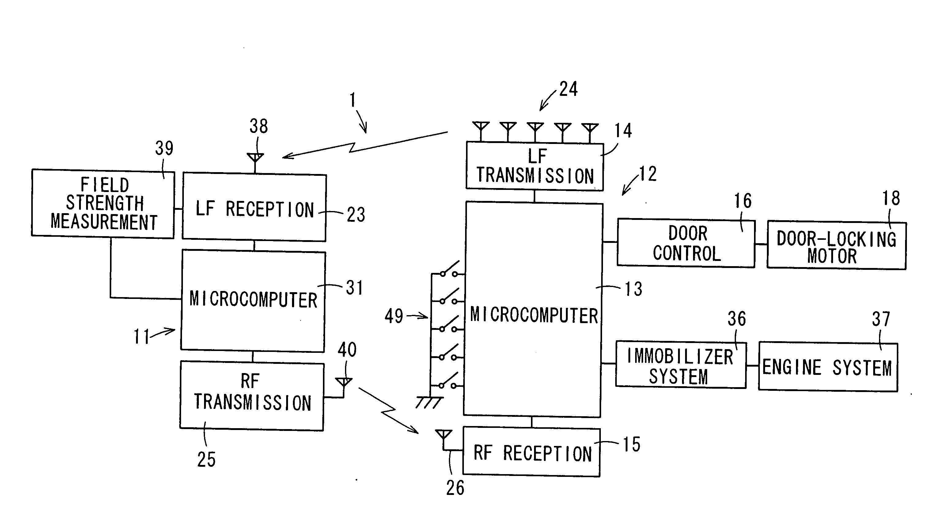
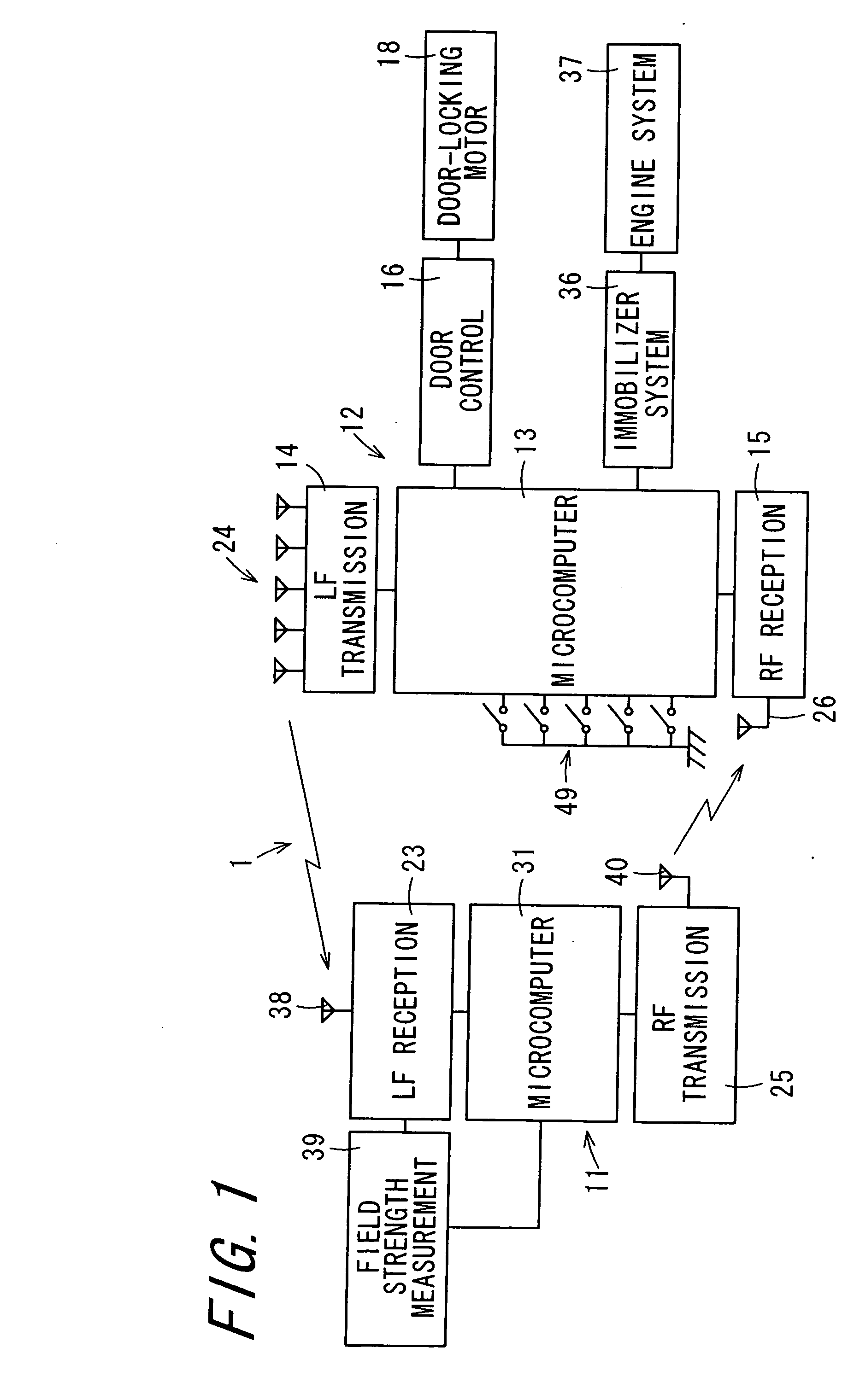
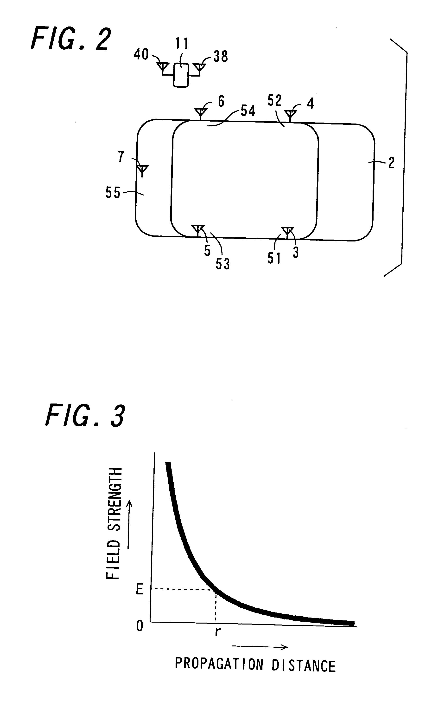
[0087]FIG. 1 is a block diagram illustrating the construction of a keyless entry system including a vehicle control system 1 according to one embodiment of the invention. FIG. 2 is a pattern diagram illustrating the position relationship between a vehicle 2 and a smart key 11 that is a portabl...

embodiment 2

[0196] A vehicle control apparatus according to the present embodiment is preferably applied to a so-called smart entry system of a vehicle. Descriptions hereinbelow include descriptions of a method of controlling a vehicle. FIG. 23 is a block diagram illustrating an electrical configuration of the vehicle control apparatus 1A according to one embodiment of the invention. FIG. 24 is a plan view illustrating the relationship between the respective transmission antennas 3 to 7 for the vehicle 2, and a vehicle-inside area 8, a vehicle-outside area 9 and an out-of-range 10. These areas will be defined later. The vehicle control apparatus 1A is an apparatus for remotely controlling the vehicle 2 through identification of a relative position between the vehicle 2 and a smart key 11 by use of radio waves. The vehicle control apparatus 1A includes a main control portion 12 provided in the vehicle 2 and the smart key 11 serving as a portable unit which can be carried. The main control portio...

embodiment 3

[0232]FIG. 27 is a block diagram illustrating a constitution of the vehicle control apparatus 1A according to one embodiment of the invention. In the embodiment, portions corresponding to the configuration described in the above-described embodiment will be denoted by the same reference numerals or symbols, and description thereof will be omitted. The configuration of the vehicle control apparatus 1B according to the present embodiment is similar to the configuration of the vehicle control apparatus 1A according to the above-described embodiment, except that a navigation system NS and an engine starter system E / GS are further provided in the vehicle control apparatus 1B. The navigation system NS serving as detecting means for vehicle position and the engine starter system E / GS serving as remote starting means for driving source are connected to the input / output interface of the main microcomputer 13, respectively.

[0233]FIG. 28 is a flowchart illustrating a process of reducing load ...


PUM


Abstract

A main control portion of a vehicle has an LF transmission antenna for transmitting a search signal. The LF transmission antenna has five antennas respectively provided on door knobs of the vehicle. A smart key receives the search signals transmitted from respective antennas constituting the LF transmission antenna, and then measures a filed strength of the received search signal. The smart key transmits field strength information representing the measured field strength to the main control portion. The main control portion calculates relative position information of the vehicle to the smart key, based on the field strength information. On the basis of the relative position information, the main control portion controls the door of the vehicle to be locked or unlocked.

Description

BACKGROUND OF THE INVENTION [0001] 1. Field of the Invention [0002] The present invention relates generally to a vehicle control system capable of remotely controlling a vehicle through wireless communication, for example, to a technology applicable to a smart entry system in order to simplify the key manipulation of a vehicle or to eliminate the key manipulation. [0003] Further, the invention relates to a vehicle control apparatus, for example, to a technology in which authentication is performed through radio waves according to the relative position between a vehicle and a portable device to remotely control the vehicle. [0004] In the invention, a driving source includes an engine and a drive motor. [0005] 2. Description of the Related Art [0006] As shown in Japanese Unexamined Patent Publication JP-A 2002-77972, for example, there has been a wireless apparatus having a main body installed in a vehicle, and a portable device for performing wireless communication with the main body...

Claims


Application Information

Patent Timeline
IPC IPC(8): G05B19/00
CPCG07C9/00309G07C2209/63
Inventor MATSUBARA, MANABUTAKASUKA, HIROFUMIMATSUURA, AKIRA
Owner FUJITSU GENERAL LTD
Why Eureka
Try Eureka