Image sensing system for a vehicle

a technology of image sensing and vehicle, applied in vehicle cleaning, optical radiation measurement, instruments, etc., can solve the problems of affecting affecting the perception of vehicles, objects, and other road users, and affecting the perception of forward-looking visual activities of drivers. , to achieve the effect of enhancing the interpretation of visual information

Inactive Publication Date: 2007-05-17
DONNELLY CORP
View PDF99 Cites 274 Cited by
  • Summary
  • Abstract
  • Description
  • Claims
  • Application Information

AI Technical Summary

Benefits of technology

[0007] The present invention is directed towards enhancing the interpretation of visual information in a rearview vision system by presenting information in a manner which does not require significant concentration of the driver or present distractions to the driver. This is accomplished according to the invention in a rearview vision system having at least two image capture devices positioned on the vehicle and directed rearwardly with respect to the direction of travel of the vehicle. A display is provided for images captured by the image capture devices. The display combines the ca...

Problems solved by technology

Furthermore, rearview mirrors protrude a substantial distance from the side of the vehicle, which makes maneuvering in tight spaces more difficult.
The driver cannot perceive vehicles, objects, or other road users in such blind spots without turning his or her body, which interferes with forward-looking visual activities.
Camera-based rearview vision systems for vehicles have not obtained commercial acceptance.
One difficulty with proposed systems has been that they present a large amount of visual information in a manner which is difficult to comprehend.
This difficulty arises from many factors.
This may confuse the driver as to whether more than one object is present.
This results in different vertical positions on the display causing the elongated image to appear disjointed.
This makes the ability to judge distances in a camera system a problem.
Therefore, known camera sy...

Method used


Image

  • Image sensing system for a vehicle
  • Image sensing system for a vehicle
  • Image sensing system for a vehicle

Examples


Embodiment Construction

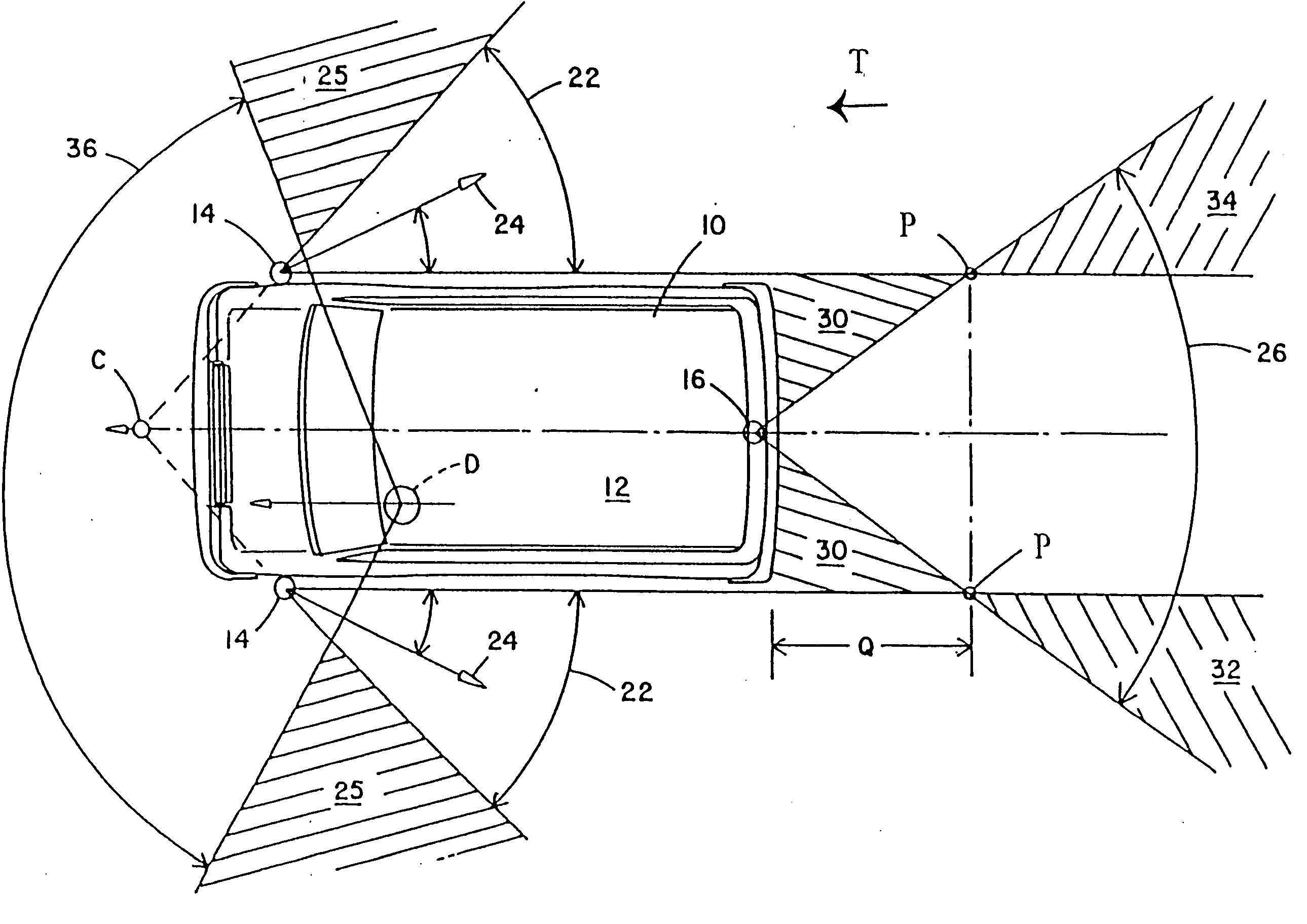
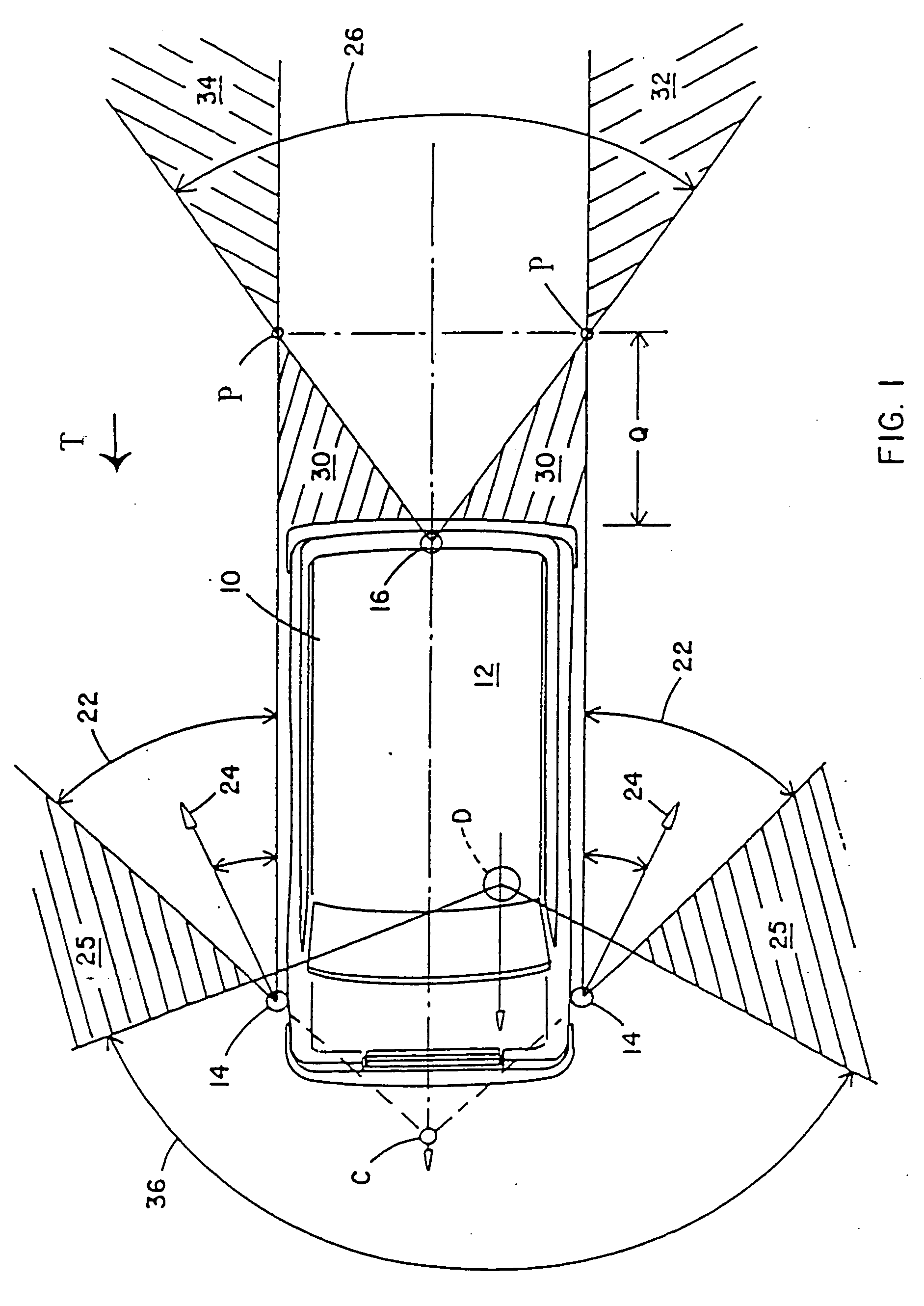
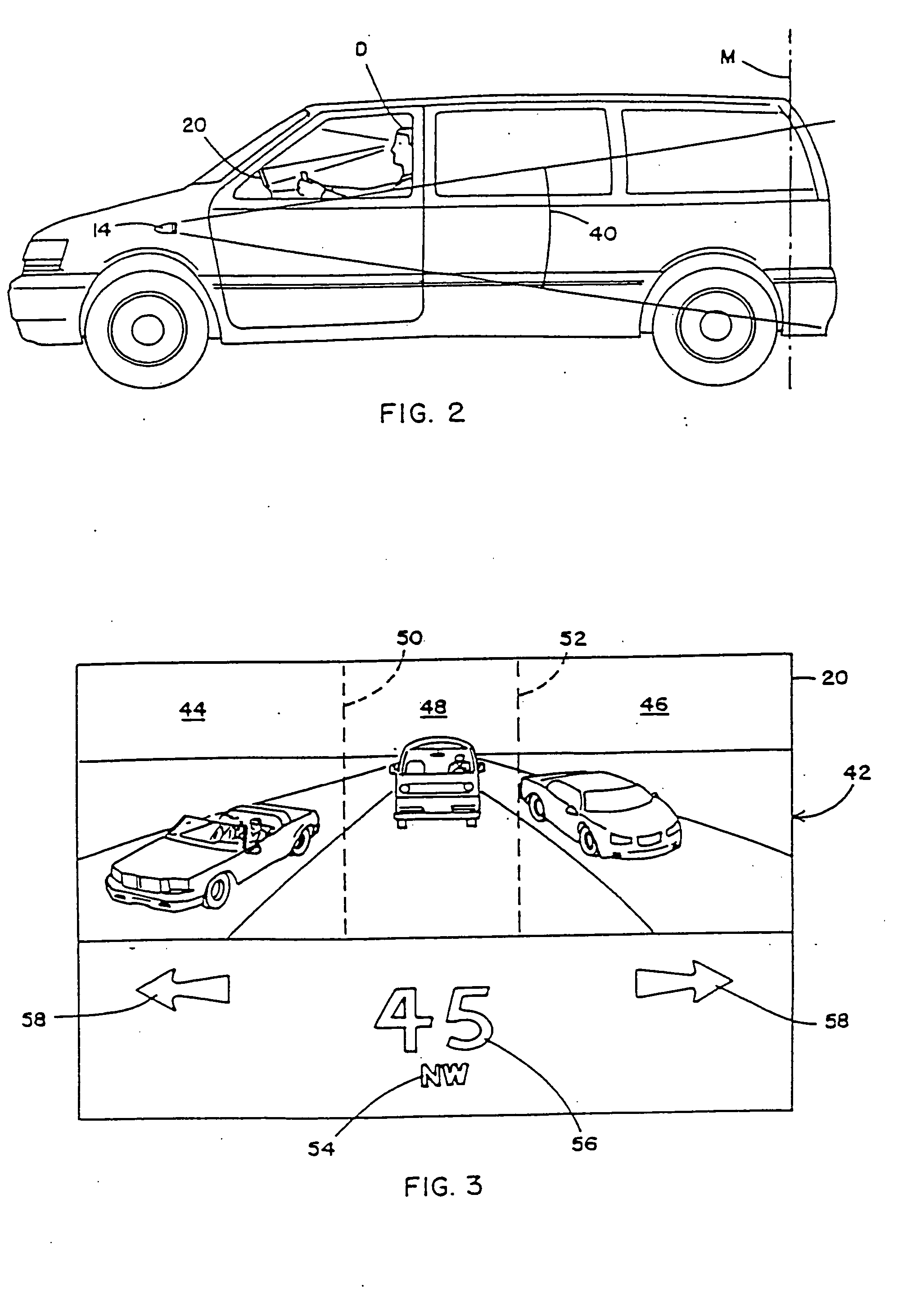
[0024] Referring now specifically to the drawings, and the illustrative embodiments depicted therein, a vehicle 10, which may be an automobile, a light truck, a sport utility vehicle, a van, a bus, a large truck, or the like includes a rearview vision system, generally illustrated at 12, for providing a driver of the vehicle with a view rearwardly of the vehicle with respect to the direction of travel D of the vehicle (FIG. 1). Vision system 12 includes at least two side image capture devices 14 positioned, respectively, on opposite sides of vehicle 10 and a center image capture device 16 positioned on the lateral centerline of the vehicle. All of the image capture devices are directed generally rearwardly of the vehicle. Rearview vision system 12 additionally includes an image processor 18 for receiving data signals from image capture devices 14, 16 and synthesizing, from the data signals, a composite image 42 which is displayed on a display 20.

[0025] As will be set forth in more ...


PUM


Abstract

An image sensing system for a vehicle includes an imaging sensor comprising a two-dimensional array of light sensing photosensor elements. The system includes a logic and control circuit comprising an image processor for processing image data derived from the imaging sensor. The logic and control circuit generates at least one control output for controlling at least one accessory of the vehicle. The imaging sensor is disposed at an interior portion of the cabin of the vehicle and preferably has a field of view exterior of the vehicle through a window of the vehicle.

Description

CROSS-REFERENCE TO RELATED APPLICATIONS [0001] The present application is a continuation of U.S. patent application Ser. No. 10 / 643,602, filed Aug. 19, 2003 (Attorney Docket DON01 P-1087), which is a continuation of application Ser. No. 09 / 776,625, filed on Feb. 5, 2001, now U.S. Pat. No. 6,611,202, which is a continuation of application Ser. No. 09 / 313,139, filed on May 17, 1999, now U.S. Pat. No. 6,222,447, which is a continuation of application Ser. No. 08 / 935,336, filed on Sep. 22, 1997, now U.S. Pat. No. 5,949,331, which is a continuation of application Ser. No. 08 / 445,527, filed on May 22, 1995, now U.S. Pat. No. 5,670,935, which is a continuation-in-part of patent application Ser. No. 08 / 023,918, filed Feb. 26, 1993, by Kenneth Schofield and Mark Larson, now U.S. Pat. No. 5,550,677.BACKGROUND OF THE INVENTION [0002] This invention relates generally to vision systems for vehicles and, more particularly, to rearview vision systems which provide the vehicle operator with scenic ...

Claims


Application Information

Patent Timeline
IPC IPC(8): H04N7/18B60R1/04B60N2/00B60Q1/08B60Q1/14B60Q1/52B60R1/00B60R1/06B60R1/08B60R1/12B60R11/04B60R21/01B60R21/015B60S1/08H04N13/239
CPCB60N2/002B60R21/01538B60Q1/1423B60Q9/008B60Q2300/054B60Q2300/056B60Q2300/21B60Q2300/314B60Q2300/3321B60Q2300/41B60Q2300/42B60R1/00B60R1/088B60R1/12B60R11/04B60R2001/1223B60R2001/1253B60R2300/101B60R2300/103B60R2300/105B60R2300/106B60R2300/107B60R2300/205B60R2300/207B60R2300/30B60R2300/302B60R2300/303B60R2300/304B60R2300/305B60R2300/307B60R2300/404B60R2300/50B60R2300/802B60R2300/8026B60R2300/804B60R2300/8053B60R2300/806B60R2300/8066B60R2300/8086B60R2300/8093B60S1/0822B60S1/0844B60S1/0885G01J1/4204G01J1/4228H04N7/181H04N13/0239H04N2013/0081H04N7/18B60Q1/14G08G1/167H04N13/239
Inventor SCHOFIELD, KENNETHLARSON, MARK L.VADAS, KEITH J.
Owner DONNELLY CORP
Why Eureka
Try Eureka