
Wireless multi-hop network, terminal and bandwidth ensured communication method for use therewith

Inactive Publication Date: 2007-05-17
NEC CORP
View PDF2 Cites 30 Cited by
  • Summary
  • Abstract
  • Description
  • Claims
  • Application Information

AI Technical Summary

Benefits of technology

[0017] Thus, the present invention has been achieved to solve the above-mentioned problems, and the objective of the invention is to provide end-to-end communication in wireless multi-hop networks, a terminal and a bandwidth ensured communication method in which the stable bandwidth ensured communication can be made without collisions of time slots due to terminals movement and reallocation of slots due to change of routes.
[0021] That is, the wireless multi-hop network of the invention is controlled by the TDMA (Time Division Multiple Access), the time slot information reserved for transmitting the packet is stored in an option header of the packet, and the forwarding terminal transmits (forwards) the packet by using the time slot obtained from the information of the option header. Thereby, in the wireless multi-hop network of the invention, the stable and bandwidth ensured communication can be made from the source terminal to the destination terminal.
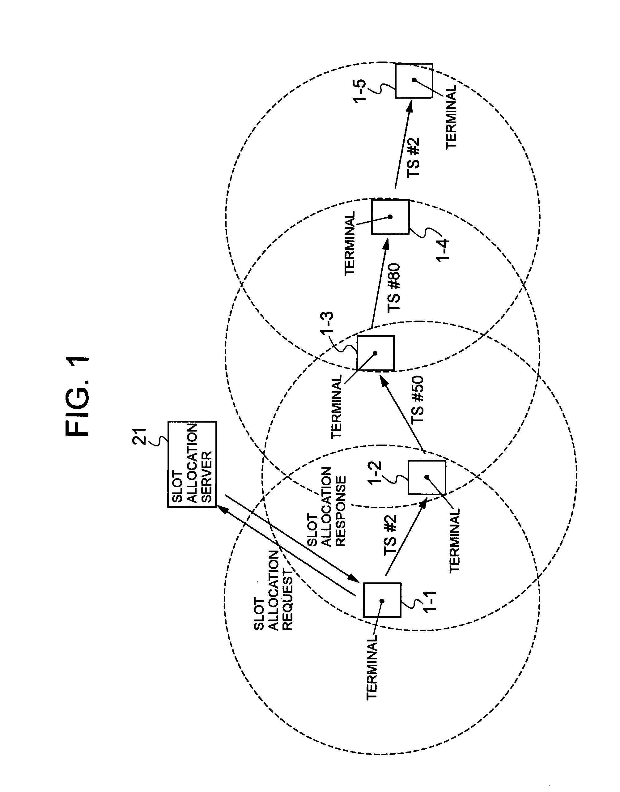
[0028] That is, in the wireless multi-hop network of the invention, the terminal makes a slot allocation request for 3 Hops (triple the slots of required bandwidth) to the slot allocation server, and a unique slot within the network is allocated by the slot allocation server, whereby there is no interference with the slot by other terminals.
[0030] Thereby, in the wireless multi-hop network of the invention, since the stable, end-to-end bandwidth ensured communication is allowed in the wireless multi-hop network, the stable bandwidth ensured communication can be made without causing a collision of time slots when the terminal moves or reserving the slot again due to a path change on the end-to-end communication in the wireless multi-hop network.

Problems solved by technology

However, in the wireless multi-hop network, because each terminal moves autonomously, when other terminals using the same slot come closer, collision of the transmission in the slot causes to disable the communication with the conventional method for reserving the time slot with the adjacent terminal only.
The conventional slot reservation method often fails and takes a lot of time, because it is dynamic.
Therefore, the communication must stop for a long time or may break.

Method used


Image

  • Wireless multi-hop network, terminal and bandwidth ensured communication method for use therewith
  • Wireless multi-hop network, terminal and bandwidth ensured communication method for use therewith
  • Wireless multi-hop network, terminal and bandwidth ensured communication method for use therewith

Examples


first embodiment

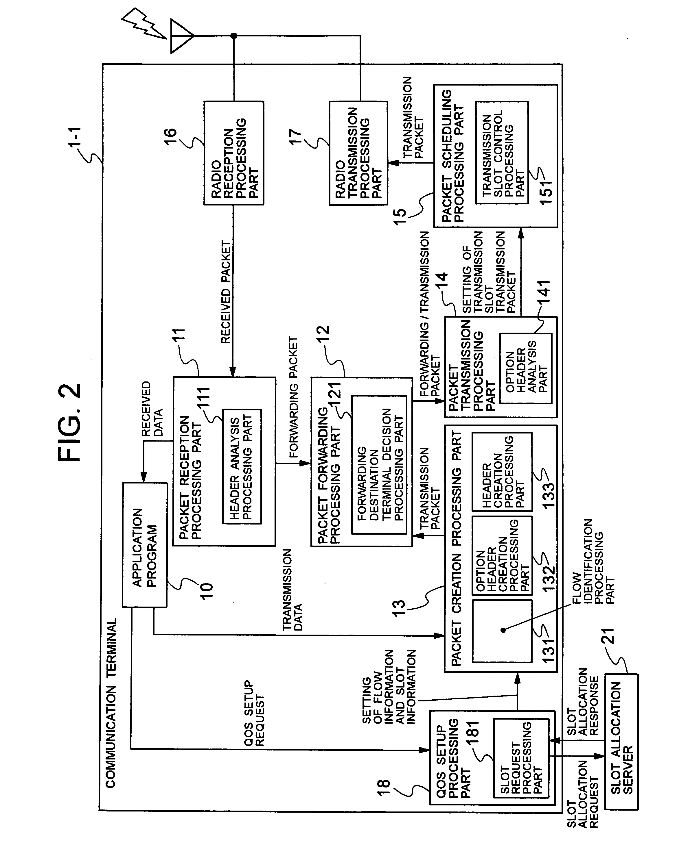
[0053]FIG. 2 is a block diagram showing the functional configuration of the terminals 1-1 to 1-5 according to the invention. In FIG. 2, the terminal 1-1 comprises an application program (hereinafter referred to as an application) 10, a packet reception processing part 11, a packet forwarding processing part 12, a packet creation processing part 13, a packet transmission processing part 14, a packet scheduling processing part 15, a radio reception processing part 16, a radio transmission processing part 17, and a QoS (Quality of Service) setup processing part 18.

[0054] Also, the packet reception processing part 11 comprises a header analysis processing part 111, the packet forwarding processing part 12 comprises a forwarding destination terminal decision processing part 121, and the packet creation processing part 13 comprises a flow identification processing part 131, an option header creation processing part 132 and a header creation processing part 133. The packet transmission pro...

second embodiment

[0094]FIG. 12 is a diagram showing a forwarding example of packet according to the invention, and shows the forwarding example of packet which involves reusing two slots in the case where the directional antenna is employed. In the forwarding example as shown in FIG. 12, since the radio wave transmitted by the terminal 1-3 does not reach the terminal 1-2, the slot can be reused at a cycle of two hops.

[0095]FIG. 13 is a diagram showing a transmission interference example according to a third embodiment of the invention. FIG. 14 shows an option header example with increased “Hop CYCLE” in the third embodiment of the invention. In FIG. 13, the radio wave transmission outputs are different for the terminals 1-1 to 1-5, and particularly, the output of the terminal 1-4 is so great that the radio wave can reach the terminal 1-2. In this case, if the terminal 1-4 reuses the slot No. 1, the radio wave from the terminal 1-4 interferes with the transmission from the terminal 1-1 to the termina...

third embodiment

[0102] One of the reasons for frequent reception error in the reserved slot at the forwarding terminal may be a change in the interference range or a change in the topology when each terminal moves, besides the above case. A distinction from the invention is made by judging whether or not the terminal 1-2 has the unidirectional link to the terminal 1-4 in the case as shown in FIG. 14 (the unidirectional link can be treated as Asymmetric Neighbor in T. Clause and one other, “Optimized Link State Routing Protocol (OLSR)”, IETF RFC 3626, October 2003, for example).

[0103] In this case, the communication path can be updated to solve the reception error by making a trigger of transmitting a control message to the routing protocol to prompt the route update.

[0104] Also, the number of slots without interference is estimated in consideration of a distribution situation for other terminals obtained from the routing protocol or interference frequency in the communication so far, and the numbe...


PUM


Abstract

To provide a wireless multi-hop network in which the stable bandwidth ensured communication can be made without causing a collision of time slots due to the terminal movement or reserving the slot again due to a route change on the path of end-to-end communication. A terminal makes a slot allocation request for 3 Hops to a slot allocation server. Since unique slots within the network are allocated by the slot allocation server, there is no interference with the slots by other terminals. The terminal transmits the packet by inserting the slot information into an option header. A forwarding terminal that forwards the packet decides the transmission slot based on the slot information in the option header and its own hop count at the time of forwarding the packet.

Description

BACKGROUND OF THE INVENTION [0001] 1. Field of the Invention [0002] The present invention relates to a wireless multi-hop network, a terminal and a bandwidth ensured communication method for use therewith, and particularly to a bandwidth ensured communication method and a terminal for performing a packet forwarding via a mobile terminal as a relay node in a wireless multi-hop network controlled by a TDMA (Time Division Multiple Access) method. [0003] 2. Related Art [0004] Conventionally, a wireless multi-hop network has been well known in which the terminals can communicate with each other by radio not only directly, but also via a relay node composed of another terminal existing within a radio communication range where the radio signal is reachable to enable transmission or reception of data between the terminals beyond the radio communication range. [0005] This wireless multi-hop network consists of a plurality of terminals, and each terminal has a router function of forwarding th...

Claims


Application Information

Patent Timeline
IPC IPC(8): H04J3/16
CPCH04L45/42H04W28/04H04W28/20H04W40/04H04W72/0406H04W72/20
Inventor YAGYUU, TOMOHIKOJIBIKI, MASAHIRO
Owner NEC CORP
Learn More