Array speaker apparatus

a speaker and array technology, applied in the field of array speaker equipment, can solve the problems of short speaker line of rear speakers sp-sl and sp-sr, wrong sound image fixed position of main channels (main signals l and r), and poor sound quality

Inactive Publication Date: 2007-05-17
YAMAHA CORP
View PDF6 Cites 59 Cited by
  • Summary
  • Abstract
  • Description
  • Claims
  • Application Information

AI Technical Summary

Benefits of technology

[0012] The present invention was developed to solve the foregoing problems. An object of the invention is to provide an array speaker apparatus which can obtain an excellent sound image fixed-position in a multi-channel surround-sound system using the array speaker apparatus.

Problems solved by technology

In the digital surround-sound system, however, a plurality of speakers are disposed to disperse in the listening room Zone so that the rear speakers SP-SL and SP-SR for surround sound are disposed at the rear of the listening position U. Thus, there are drawbacks that the speaker lines of the rear speakers SP-SL and SP-SR become long, and that the layout of the rear speakers SP-SL and SP-SR is bound by the shape of the listening room Zone, furniture, etc.
While having the advantage as described above, surround-sound systems using an array speaker also have some problems in practical use.
The first problem is the point that the sound image fixed-positions of the main channels (main signals L and R) are wrong.
The second problem is the point that the sense of the sound image fixed-positions of the surround channels (rear signals SL and SR) are wrong.
In fact, however, each acoustic beam merely creates an intensive directivity distribution.
When the distance to the listener is larger, the energy of an audio signal is attenuated disadvantageously to the ratio to the direct sound.
Particularly, there is a problem in difficulty to control a low frequency.
The required array width is about 2 m, which is not the practical size for general home use.
Thus, the sound image maybe separated, or the sense of fixation thereof may be wrong.

Method used


Image

  • Array speaker apparatus
  • Array speaker apparatus
  • Array speaker apparatus

Examples


first embodiment

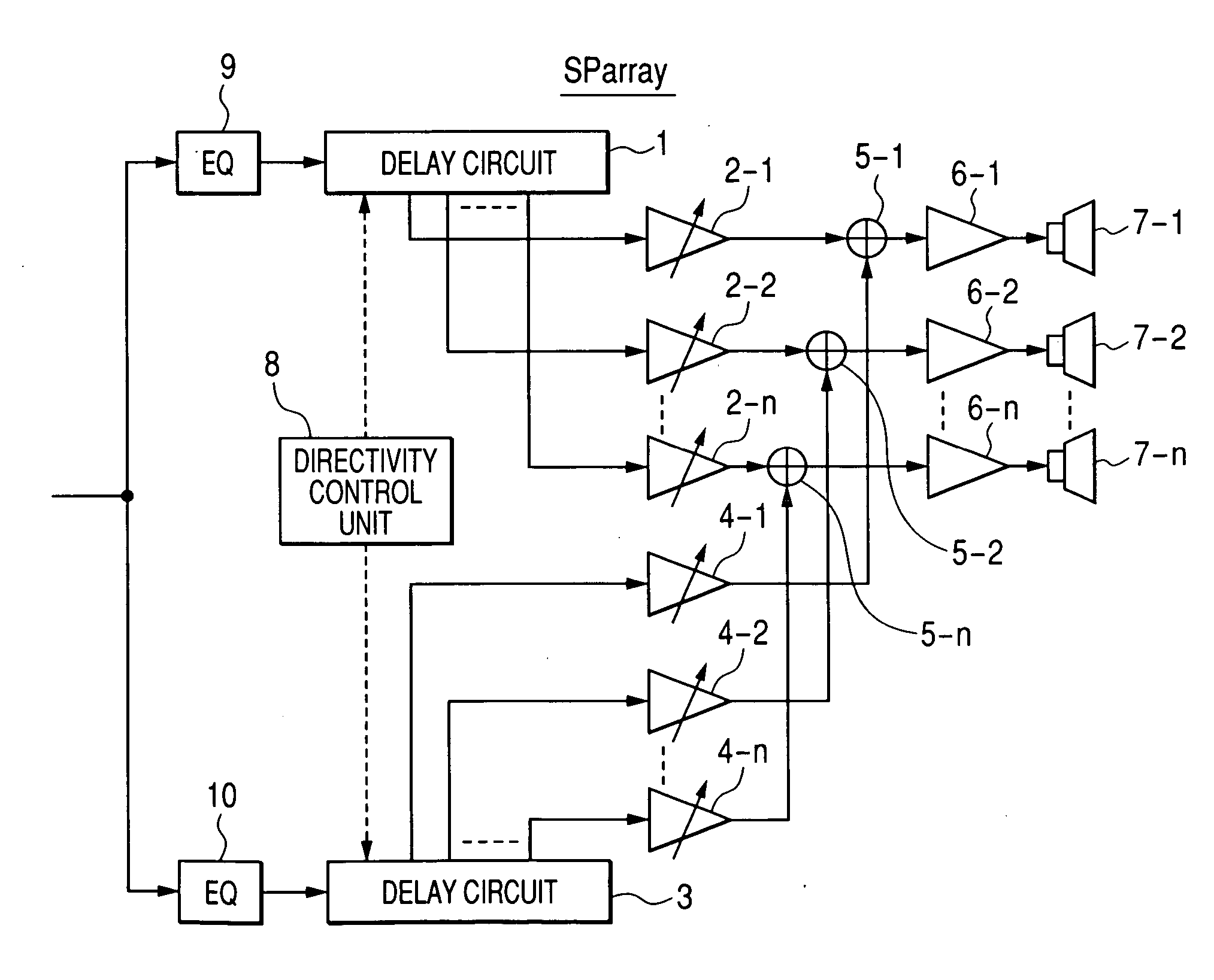
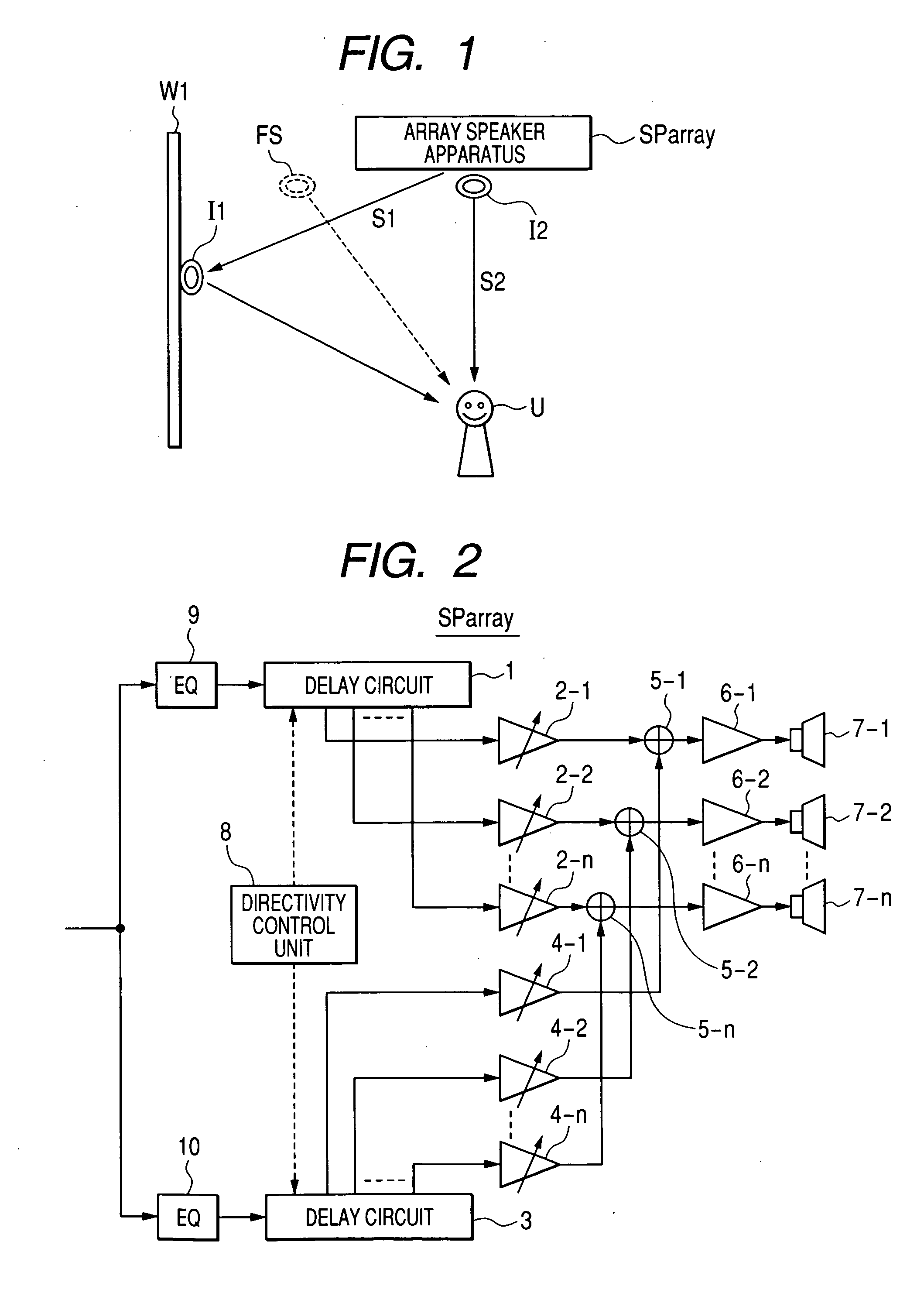
[0065] An embodiment of the present invention will be described below in detail with reference to the drawings. An array speaker apparatus SParray according to a first embodiment is constituted by a first audio signal generating circuit for generating first audio signals to be radiated to a wall surface W1 on the left or right side of a listening position U based on an input audio signal of one channel of main channels (main signals L and R), a second audio signal generating circuit for generating second audio signals to be radiated directly to the listening position U based on the input audio signal, adders for adding the first audio signals to the second audio signals, and amplifiers for amplifying the outputs of the adders, speaker units to be driven by the amplifiers, and a directivity control circuit constituted by a microcomputer or the like for deciding the directivities of the first audio signals and the second audio signals.

[0066] This array speaker apparatus SParray can b...

second embodiment

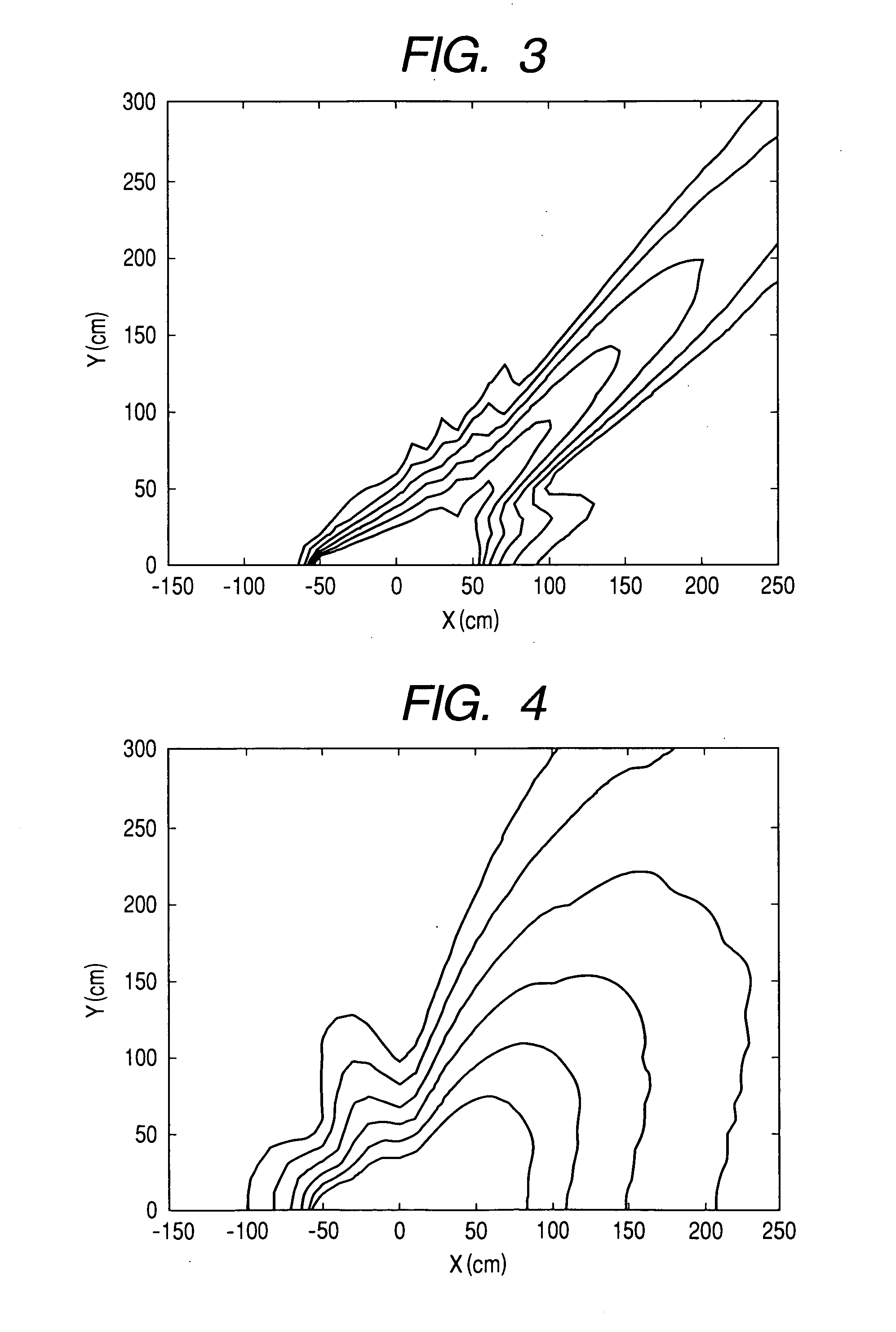
[0085] Next, description will be made about a second embodiment of the present invention. Prior to the description of the second embodiment, description will be made about a change of a beam shape due to a frequency band. When the array speaker width and the set focus are fixed, the higher the frequency is, the acuter the beam is. Each of FIGS. 3 and 4 is a graph showing a simulated example of directivity distribution when a focus was set in the direction of 45° in a background-art array speaker apparatus 95 cm wide. Each of FIGS. 3 and 4 shows contours of sound pressure levels of a single frequency on an XY plane, showing sound pressure levels when a plurality of speaker units were disposed in the X-axis direction around the position of 0 cm in the X axis. The example of FIG. 3 shows a simulated result of a sine wave of 2 kHz, and the example of FIG. 4 shows a simulated result of a sine wave of 500 Hz.

[0086] The directivity of a low frequency band is not as acute as that of a high...

third embodiment

[0109] Next, description will be made about a third embodiment of the present invention. As described in the second embodiment, the directivity of the low frequency band is not as acute as that of the high frequency band. Therefore, there is a small difference between the sound pressure energy in the radiation direction and the sound pressure energy in the frontal direction of the array speaker apparatus. On the contrary, the sound pressure of the high frequency band is attenuated suddenly in a position out of the beam center. Accordingly, a range where a frequency balance with the low frequency band is good is narrow. That is, an area where good listening can be secured is narrow. A sound closer to a natural sound and better in frequency balance has a better sense of fixed position. To this end, this embodiment is to correct a difference in directivity shape between frequency bands.

[0110] As shown in FIGS. 3 and 4, 2 kHz has much stronger directivity than 500 Hz. Here, FIG. 8 show...


PUM


Abstract

An array speaker apparatus SParray includes a first radiation means for driving speaker units so that a first sound S1 of a main channel is radiated to a wall surface W1 on the left or right side of a listening position, and a second radiation means for driving the speaker units so that a second sound S2 the same as the first audio signal is radiated directly to the listening position.

Description

TECHNICAL FIELD [0001] The present invention relates to an array speaker apparatus in which audio signals radiated from a plurality of speaker units are reflected by wall surfaces so as to generate a virtual sound source. BACKGROUND ART [0002] Recently, in some audio sources such as DVD, multi-channel audio signals of 5.1 channels or the like are recorded. Digital surround-sound systems for reproducing such audio sources have been dominating even in general homes. FIG. 10 is a plan view showing an example of a speaker layout in a digital surround-sound system, in which Zone represents a listening room where surround-sound is reproduced; U, a listening position; SP-L and SP-R, main speakers for reproducing main signals L (left) and R (right); SP-C, a center speaker for reproducing a center signal C (center); SP-SL and SP-SR, rear speakers for reproducing rear signals SL (rear left) and SR (rear right); SP-SW, a subwoofer for reproducing a subwoofer signal LFE (lower frequency); and M...

Claims


Application Information

Patent Timeline
Patent Type & Authority Applications(United States)
IPC IPC(8): H04R1/02H04R25/00H04R1/40H04R3/00H04R3/04H04R3/12H04S3/00H04S7/00
CPCH04R1/403H04R3/12H04R2203/12H04R2205/022H04S3/00
Inventor KONAGAI, YUSUKETAKUMAI, SUSUMU
Owner YAMAHA CORP
Why Eureka
Try Eureka