Control apparatus for vehicular drive system

a control apparatus and vehicular drive technology, applied in the direction of electric propulsion mounting, machines/engines, gearing, etc., can solve the problems of not having any power transmission mechanism with advantages, and the vehicular drive system suffers from similar problems, so as to improve the efficiency of continuously variable shifting control of the continuously variable transmission portion, compact in size, and compact in size

Inactive Publication Date: 2007-05-17
TOYOTA JIDOSHA KK
View PDF6 Cites 17 Cited by
  • Summary
  • Abstract
  • Description
  • Claims
  • Application Information

AI Technical Summary

Benefits of technology

[0010] In the control apparatus constructed as described above, the continuously-variable transmission portion of the vehicular drive system is switchable by the differential-state limiting device, between a continuously-variable shifting state in which the differential mechanism has the differential function without a limitation imposed by the differential-state limiting device, to permit the continuously-variable transmission portion to be operable as the electrically controlled continuously variable transmission, and a non-continuously-variable shifting state in which the differential function of the differential mechanism is limited to the operation of the continuously-variable transmission portion. When the differential mechanism is placed in a non-differential state, for example, in a locked state, the continuously-variable transmission portion is placed in the non-continuously-variable shifting state, for example, in a step-variable shifting state in which the continuously-variable transmission portion is not operable as the electrically controlled continuously variable transmission. Accordingly, the present drive system has both an advantage of an improvement of the fuel economy of a transmission the speed ratio of which is electrically variable, and an advantage of a high power transmitting efficiency of a gear type power transmitting device constructed for mechanical transmission of power.
[0050] Further, a manually operable means may be provided to selectively place the drive system in the non-continuously-variable shifting state, for example, in the step-variable shifting state, so that the vehicle operator can manually place the drive system in the continuously-variable shifting state when the vehicle operator desires the drive system to operate as a continuously variable transmission or desires to improve the fuel economy of the vehicle, or place the vehicle drive system in the step-variable shifting state when the vehicle operator desires the drive system to operate as a step-variable transmission or desires a rhythmic change of the engine rotational speed as a result of a shifting action of the step-variable transmission.

Problems solved by technology

However, there is not available any power transmitting mechanism having the advantages of those two types of transmission.
Where the above-described differential mechanism is a transmission the speed ratio of which is electrically variable, for example, a continuously variable transmission so-called an “electric CVT”, the vehicular drive system suffers from a similar problem.

Method used


Image

  • Control apparatus for vehicular drive system
  • Control apparatus for vehicular drive system
  • Control apparatus for vehicular drive system

Examples


embodiment 1

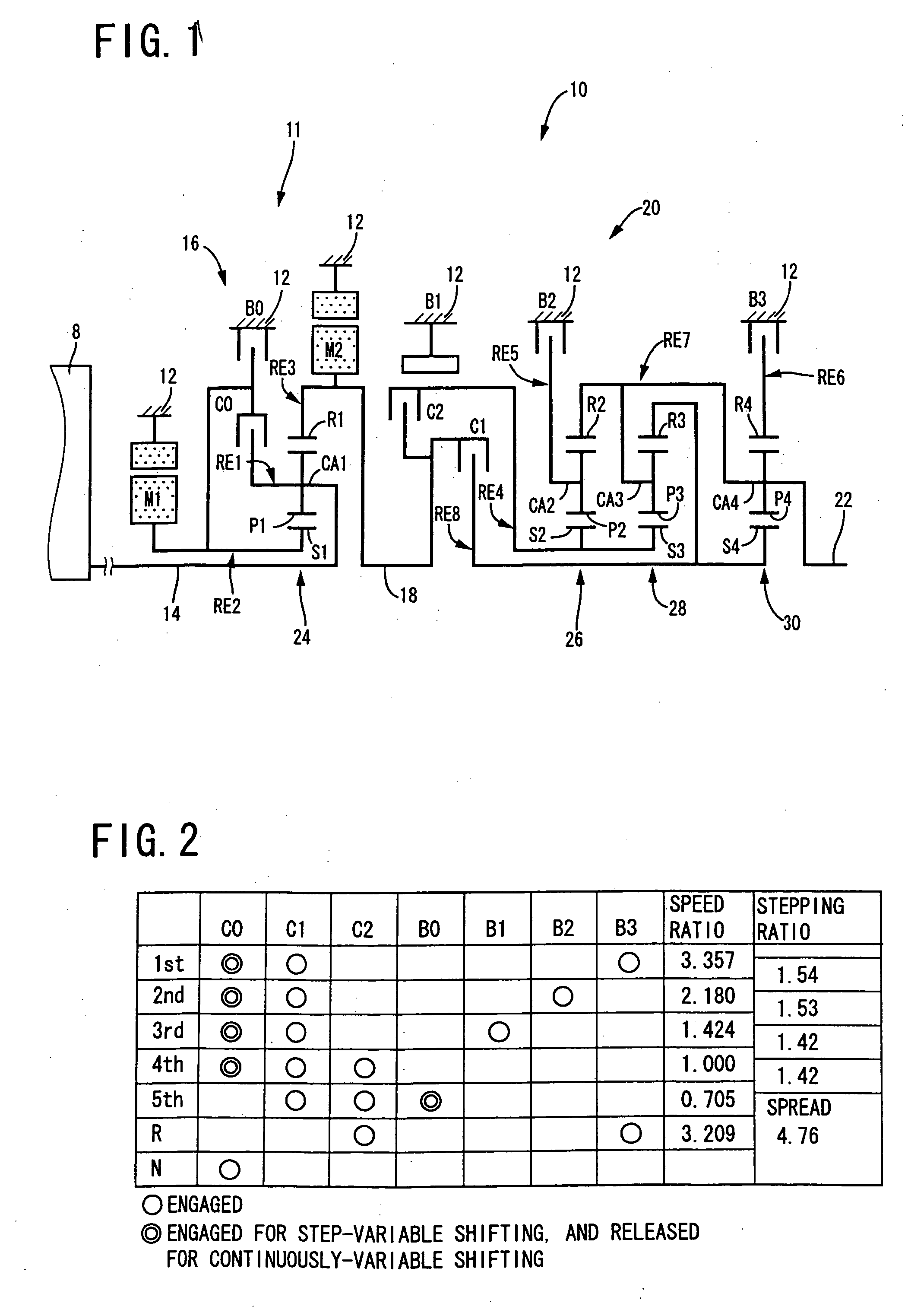
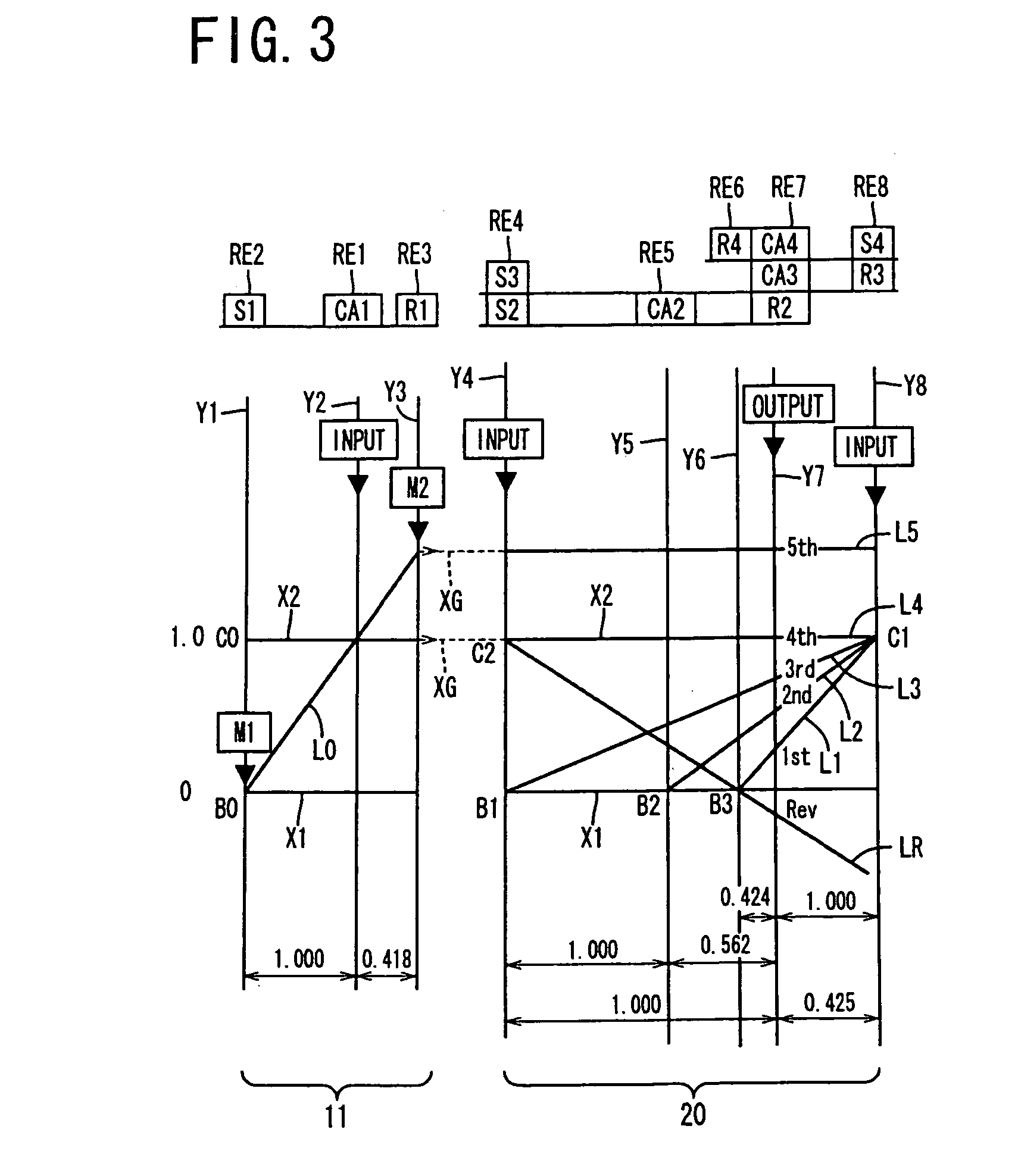
[0073] Referring to the schematic view of FIG. 1, there is shown a transmission mechanism 10 constituting a part of a drive system for a hybrid vehicle, which drive system is controlled by a control apparatus according to one embodiment of this invention. In FIG. 1, the transmission mechanism 10 includes: an input rotary member in the form of an input shaft 14; a continuously-variable transmission portion in the form of a differential portion 11 connected to the input shaft 14 either directly, or indirectly via a pulsation absorbing damper (vibration damping device) not shown; a step-variable or multiple-step transmission portion in the form of an automatic transmission portion 20 disposed between the differential portion 11 and drive wheels 38 of the vehicle, and connected in series via a power transmitting member 18 (power transmitting shaft) to the transmission portion 11 and the drive wheels 38; and an output rotary member in the form of an output shaft 22 connected to the autom...

embodiment 2

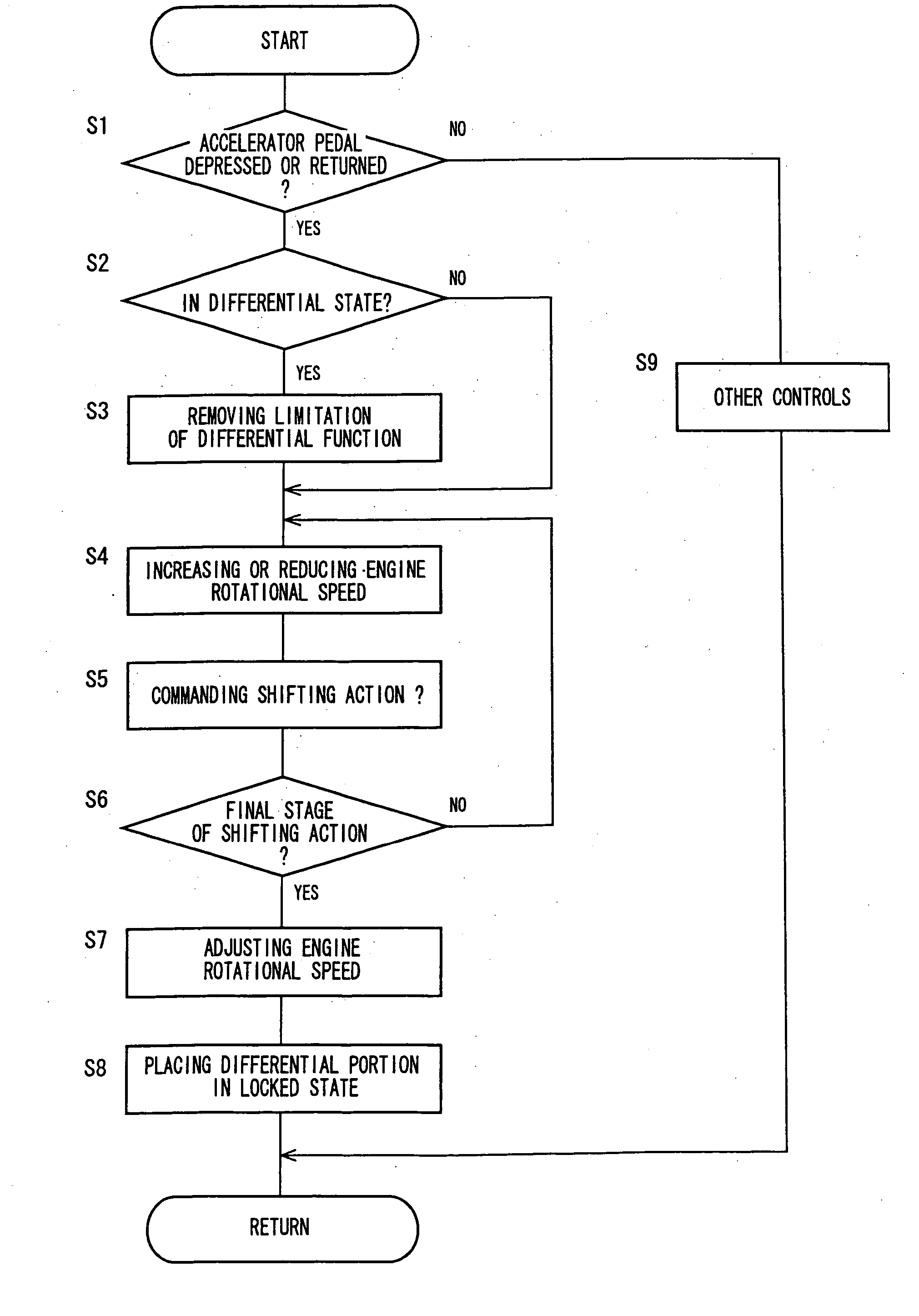
[0202] In the above-described embodiment, upon request of acceleration or deceleration of the vehicle, the switching control means 50 is arranged to hold the differential portion 11 in the continuously-variable shifting state when the differential portion 11 is in the continuously-variable shifting state, or to place the differential portion 11 in the continuously-variable shifting state when the differential portion 11 is in the non-continuously-variable shifting state, so that the engine rotational speed NE can be freely changed by the hybrid control means 52 owing to the differential function, for improving the vehicle acceleration or deceleration drivability as felt by the vehicle operation.

[0203] When acceleration or deceleration of the vehicle is required, the engine torque TE is generated according to the operating amount ACC of the accelerator pedal 45 and the vehicle speed V by the hybrid control means 52. That is, upon request of the acceleration or deceleration of the ve...

embodiment 3

[0239]FIG. 18 is a schematic view for explaining an arrangement of a transmission mechanism 70 in still another embodiment of this invention. FIG. 19 a table indicating a relationship between the gear positions of the transmission mechanism 70 and different combinations of engaged states of the hydraulically operated frictional coupling devices for respectively establishing those gear positions. FIG. 20 is a collinear chart for explaining a shifting operation of the transmission mechanism 70.

[0240] The transmission mechanism 70 includes the differential portion 11 having the first electric motor M1, power distributing mechanism 16 and second electric motor M2, as in the preceding embodiments. The transmission mechanism 70 further includes an automatic transmission portion 72 having three forward drive positions. The automatic transmission portion 72 is disposed between the differential portion 11 and the output shaft 22 and is connected in series to the differential portion 11 and ...


PUM


Abstract

A control apparatus for a vehicular drive system including a continuously-variable transmission portion operable as an electrically controlled continuously variable transmission, the continuously-variable transmission portion having a differential mechanism operable to distribute an output of an engine to a first electric motor and a power transmitting member, and a second electric motor disposed in a power transmitting path between the power transmitting member and a drive wheel of a vehicle. The control apparatus includes: (a) a differential-state limiting device provided in the differential mechanism, and operable to limit a differential function of the differential mechanism, for limiting an operation of the continuously-variable transmission portion as the electrically controlled continuously variable transmission; and (b) a differential-state switching controller operable, when acceleration or deceleration of the vehicle is required, for removing the limitation imposed by the differential-state limiting device on the operation of the continuously-variable transmission portion as the electrically controlled continuously variable transmission.

Description

[0001] The present application is based on Japanese Patent Applications No. 2005-154748 and No. 2005-184436. BACKGROUND OF THE INVENTION [0002] 1. Field of the Invention [0003] The present invention relates to a vehicular drive system including a differential mechanism having a differential function, and electric motors, and more particularly to techniques for improving a fuel economy. [0004] 2. Discussion of Prior Art [0005] There is known a drive system for a vehicle, which includes a differential mechanism operable to distribute an output of an engine to a first electric motor and its output shaft, and a second electric motor disposed between the output shaft of the differential mechanism and a drive wheel of the vehicle. Patent Document 1 discloses an example of such a vehicular drive system, which is a hybrid vehicle drive system. In this hybrid vehicle drive system, the differential mechanism is constituted by a planetary gear set, for example, and a major portion of a drive f...

Claims


Application Information

Patent Timeline
Patent Type & Authority Applications(United States)
IPC IPC(8): B60K1/02B60K6/445B60K6/547B60L15/20B60L50/16B60W10/06B60W10/08B60W10/10B60W20/00F02D29/02F16H3/72F16H59/18F16H61/02F16H61/66F16H61/68F16H61/684F16H61/686
CPCB60K1/02Y10T477/26B60K6/445B60K6/547B60W10/06B60W10/08B60W10/105B60W20/00B60W30/19F16H61/686F16H2037/0873F16H2300/14Y02T10/6286Y02T10/7258Y02T10/6239Y10T477/23Y10T477/24B60K6/365Y02T10/62Y02T10/72B60W20/10
Inventor TABATA, ATSUSHIINOUE, YUJIKAMADA, ATSUSHI
Owner TOYOTA JIDOSHA KK
Why Eureka
Try Eureka