Occlusion device and surgical instrument and method for its implantation/explantation

a technology which is applied in the field of occlusion device and surgical instrument and method for its implantation/explantation, can solve the problems of difficult and complex implantation procedure, easy material fatigue of umbrellas, and frequent prediction of thromboembolic complications, so as to achieve easy and reliable manipulation of occlusion device

Inactive Publication Date: 2007-05-17
OCCLUTECH HLDG
View PDF12 Cites 141 Cited by
  • Summary
  • Abstract
  • Description
  • Claims
  • Application Information

AI Technical Summary

Benefits of technology

[0033] For the third embodiment of the holder of an occlusion device, a surgical instrument is provided with a hook which can move axially along the eyelet, toward and away from same, by means of a push/pull system, whereby a fastening loop which extends through the eyelet and which can be hooked to the hook is used, by means of which the implant can be held to the surgical instrument by tensioning the fastening loop when the hook is moved away from the eyelet. The advantage to this embodiment of the surgical instrument is particularly noted to be that the insertion thread or guidewire is replaced by the fastening loop, thereby dispensing with the need to pull on the loose ends of said insertion thread or guidewire in order to tension the entire device as described with respect to the other two embodiments; the tensioning instead ensues from withdrawing the hook, which can follow from the appropriate actuating of the surgical instrument.
[0034] In the third embodiment of the su

Problems solved by technology

However, a disadvantage to such prior art occlusion devices turns out to be the relatively complicated, difficult and complex implantation procedure.
Apart from the complicated implantation of the occlusion system in the septal defect to be occluded, the umbrellas utilized are susceptible to material fatigue along with fragment fracture.
Furthermore, thromboembolic complications are frequently to be anticipated.
In a situation such as this, the operating surgeon cannot discern whether the occluder will assume its predetermined fit once uncoupled.
This gives rise to great uncertainty for the surgeon, in particular since his only means of repositioning an uncoupled occluder is a non-minimally invasive procedure.
However, seen as problematic with the Lock-Clamshell occluder is the fact that the insertion instruments necessary to implant the device need to be of relatively large size.
A further disadvantage seen with other systems, e.g. the so-called “Amplatz occ

Method used


Image

  • Occlusion device and surgical instrument and method for its implantation/explantation
  • Occlusion device and surgical instrument and method for its implantation/explantation
  • Occlusion device and surgical instrument and method for its implantation/explantation

Examples


first embodiment

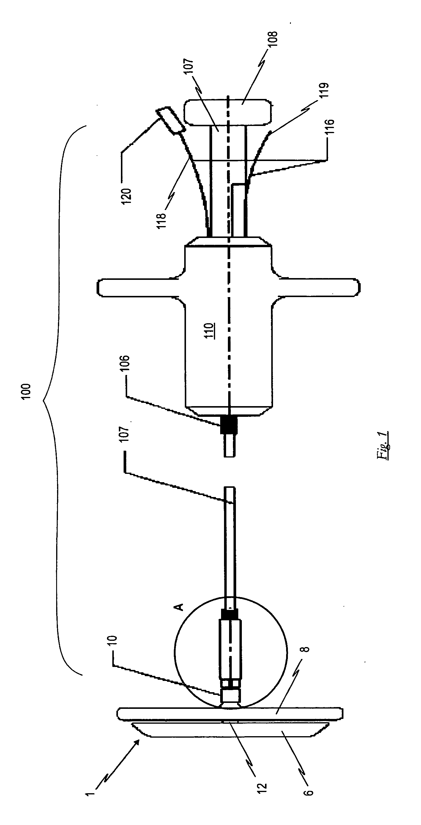
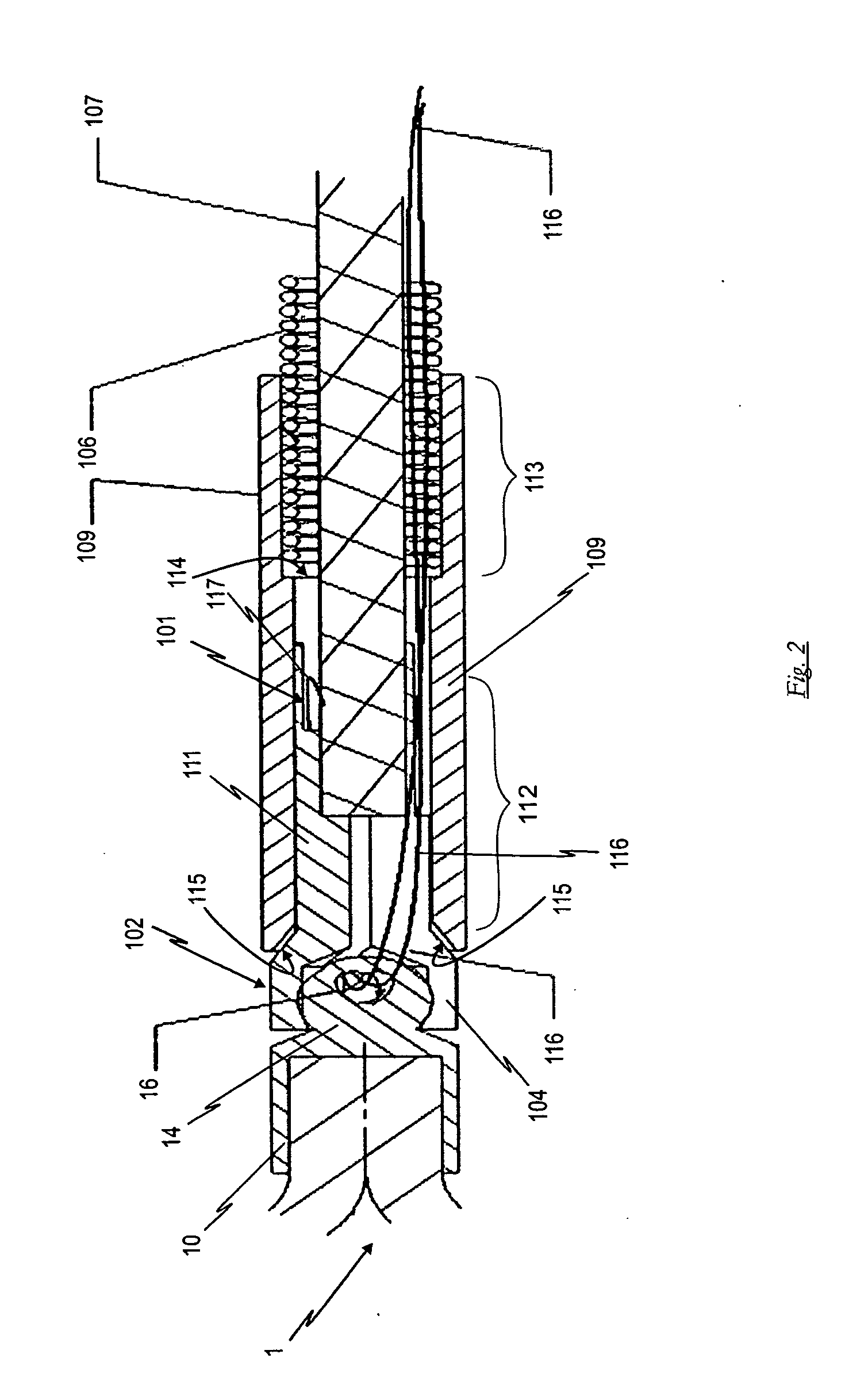
[0067]FIGS. 1 and 2 show a side and detail view of a surgical instrument 100 for the implantation and explantation of an implant serving here as an example of an implant coupled to an occlusion device 1. Surgical instrument 100 exhibits gripper tongs 102, the gripping jaws 103, 104, 105 of which can be opened and closed by means of a push / pull system. The inside areas of gripping jaws 103, 104, 105 are configured such that they can grab the spherically-configured head section 14 of holder 10 of the implant in a force-fit lock. The push / pull system essentially comprises the following components: a coil spring 106, through the interior of which an actuator means 107 extends which is rigid in the axial direction yet still sufficiently flexible, a shaft 111 of gripper tongs 102 being affixed at its proximal end and a first gripping section 108 disposed at its distal end. The push-pull system additionally comprises a taper sleeve 109 which receives the shaft 111 of the axially-displaceab...

second embodiment

[0080]FIG. 12 shows a simplified representation of the forward section of surgical instrument 200 with loop 117 protruding from the tip of gripper tongs 102 and the occlusion device 1 to be coupled, all in accordance with the

[0081]FIG. 13 shows an enlarged detail view of gripper tongs 102 with loop 117 of insertion thread / guidewire 116 protruding from between gripping jaws 103, 104, 105 (gripping jaws 104, 105 are not visible in this representation).

[0082]FIG. 14 shows a representation similar to that of FIG. 12, wherein FIG. 14 shows surgical instrument 200 already having been connected to occlusion 1.

[0083] The push / pull system of the second embodiment of surgical instrument 200 consists of the same components as was described above with respect to the first embodiment.

[0084] The method for the repeatable coupling of an implant having a holder 10 of the second embodiment, an occlusion device 1 in particular, to a surgical instrument 100 in accordance with the second embodiment ...

third embodiment

[0087]FIG. 20 shows a perspective representation of cylindrical sleeve 304 of surgical instrument 300 in accordance with the Cylindrical sleeve 304 exhibits a continuous first longitudinal groove 306 at the proximal forward side 304, a second longitudinal groove 307 at one side of its center section for anti-twist guidance of the axially-displaceable hook 302 in the sleeve, and a cross-groove 308 at a right angle to the second longitudinal groove 307 on the one side which extends to the longitudinal axis of sleeve 304 and has a protrusion 309 at its center for receiving a knot 311 of fastening loop 301. The second longitudinal groove 307 is thus configured such that it cuts through the circumference of sleeve 304 from outer to inner diameter.

[0088]FIG. 21 shows a perspective representation of hook 302 with its shaft 303. The cross-section of the forward section of hook 302 is configured to be about one-third flatter than the cross-section of shaft 303, indicated by reference numera...


PUM


Abstract

An occlusion device includes a braiding of thin wires or threads tapering to the diameter of a catheter used for an intravascular implantation/explantation procedure and having a proximal retention area, a distal retention area at which ends of the wires or threads converge into a holder, and a cylindrical crosspiece interposed between the proximal retention area and the distal retention area, whereby the two retention areas are positioned on two sides of a shunt to be occluded in a septum following implantation while the crosspiece transverses the shunt. The holder exhibits a head section at its free end having an eyelet as a cross-hole which can be gripped and held in form-fit fashion by an implantation/explantation instrument. A surgical instrument having such a holder includes gripper tongs with gripping jaws which open and close by a push/pull system, and which force-fit grips the head section of the holder.

Description

[0001] The present invention relates to an occlusion device and a surgical instrument for the implantation / explantation of an implant. BACKGROUND OF THE INVENTION [0002] 1. Field of the Invention [0003] The present invention relates to an occlusion device consisting of a braiding of thin wires given a suitable form by means of a molding and heat treatment procedure and which tapers to the diameter of a catheter used for an intravascular implantation or explantation procedure having a proximal retention area, a distal retention area, at which the ends of the wires or threads converge into a holder, and having a cylindrical crosspiece interposed between said proximal retention area and said distal retention area, whereby the two retention areas position on the two sides of a shunt to be occluded in a septum following implantation while the crosspiece transverses the shunt. The invention moreover relates to a surgical instrument for the implantation and explantation of an implant, in p...

Claims


Application Information

Patent Timeline
IPC IPC(8): A61B17/08
CPCA61B17/0057A61B2017/00575A61B2017/00592A61B2017/00606A61B2017/00619A61B2017/00623
Inventor FIGULLA, HANS REINERMOSZNER, FRIEDRICHMOSZNER, ROBERTOTTMA, RUDIGER
Owner OCCLUTECH HLDG
Why Eureka
Try Eureka