Video distribution apparatus, viewer apparatus, video distribution system including these apparatuses, control method for the video distribution apparatus, control method for the viewer apparatus, and computer program for the apparatuses

a video distribution and viewer technology, applied in the field of video distribution techniques for distributing video images via a network, can solve the problems of inability to perform flexible switching between electronic ptz distribution mode and mechanical ptz emulation distribution mode, prior art, and inability to provide video images, etc., to achieve the effect of improving flexibility in the switching of distribution mod

Inactive Publication Date: 2007-05-17
CANON KK
View PDF2 Cites 56 Cited by
  • Summary
  • Abstract
  • Description
  • Claims
  • Application Information

AI Technical Summary

Benefits of technology

[0008] It is an object of the present invention to provide a video distribution apparatus, a viewer apparatus, and a video distribution system including these apparatuses, which are enhanced in f

Problems solved by technology

However, in general, the electronic PTZ cannot provide a video image (intermediate video image) picked up during the panning, tilting, or zooming operation, which the mechanical PTZ can provide.
However, in the conventional video distribution system, it

Method used


Image

  • Video distribution apparatus, viewer apparatus, video distribution system including these apparatuses, control method for the video distribution apparatus, control method for the viewer apparatus, and computer program for the apparatuses
  • Video distribution apparatus, viewer apparatus, video distribution system including these apparatuses, control method for the video distribution apparatus, control method for the viewer apparatus, and computer program for the apparatuses
  • Video distribution apparatus, viewer apparatus, video distribution system including these apparatuses, control method for the video distribution apparatus, control method for the viewer apparatus, and computer program for the apparatuses

Examples


first embodiment

[0049] In the embodiments of the present invention, video images are distributed from an electronic PTZ function-equipped video distribution apparatus (e.g. a camera server or a network camera) via a network to viewer apparatuses (e.g. PCs executing a viewer program). Particularly in a first embodiment, a description will be given of a method of carrying out video mode switching e.g. between an electronic PTZ mode and a mechanical PTZ emulation mode based on control information (e.g. a request or a command) sent from a viewer apparatus according to operations by an operator.

[0050] In the following description, mode switching is performed in response to an operation of an operating control (e.g. a scroll bar or a select box) as a part of a viewer interface. It should be noted that correspondences between operating controls (also referred to as “operating components”) and mode designating information items) are stored e.g. in a mapping table provided in the viewer apparatus.

[0051]FIG...

second embodiment

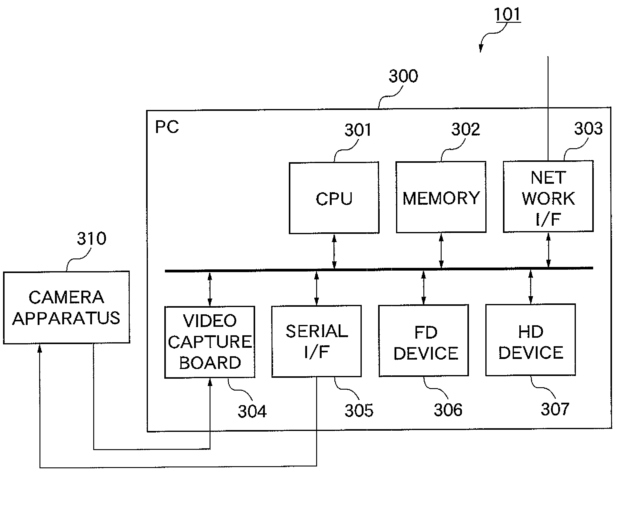
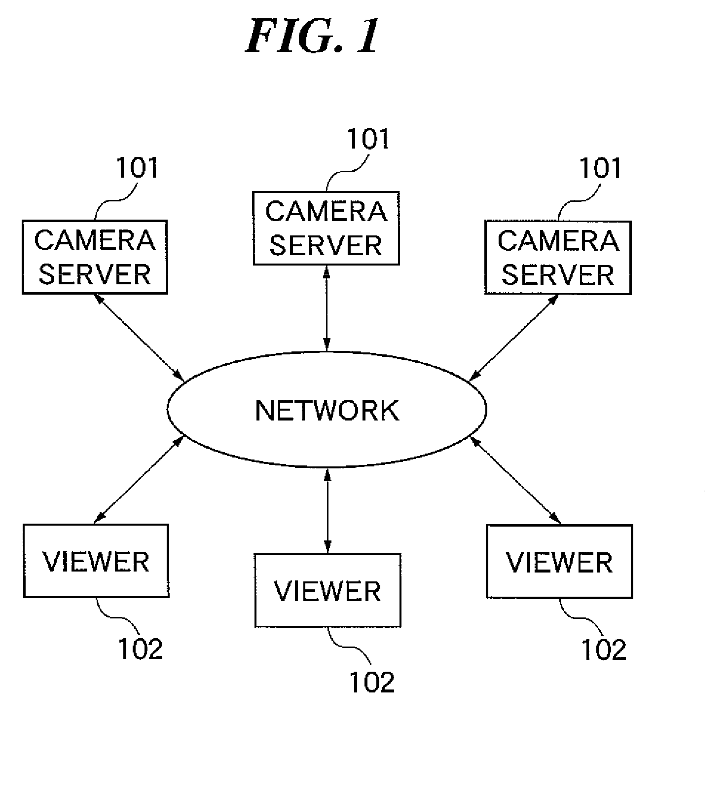
[0064]FIG. 6 is a flowchart of a control process executed by each camera server in FIG. 1. In a step S601, the CPU 301 of the camera server 101 determines, based on control information received from a viewer 102 through the network I / F 303, whether or not mode switching is to be performed. The CPU 301 performs this determination e.g. by determining whether or not the control information contains mode designating information explicitly designating mode switching. Alternatively, as described in detail hereinafter in a second embodiment, the determination may be performed by the CPU 301 based on a mapping table in which correspondences between predetermined control information items and the modes are registered. The mapping table is stored e.g. in the memory 302 or the HD device 307. If it is determined in the step S601 that mode switching is to be performed, the CPU 301 further determines which mode is to be selected, followed by the process proceeding to a step S602. On the other han...

third embodiment

[0124] Next, a description will be given of the present invention.

[0125] In the first and second embodiments, a viewer 102 or a camera server 101 controls an associated camera in a suitable mode in response to an operating control or an operation command.

[0126] In the third embodiment, a description will be given of a case where, as in the first embodiment, a suitable mode is designated in response to operation of the user interface of a viewer, and an associated camera is controlled in accordance with the designated mode, and particularly of the relationship between issuing of each camera control command or video control command, associated processing, and the viewer interface. It should be noted that description of component parts and elements in the third embodiment identical to those of the first or second embodiment is omitted so as to avoid repetition and duplication.

[0127]FIG. 18 is a flowchart of a process in which a viewer 102 establishes connection to the video server 50...


PUM


Abstract

A video distribution system which is enhanced in flexibility in distribution mode switching. In a camera server connected to a viewer via a network, a video capture board captures a video image. A CPU processes the captured video image according to an electronic PTZ mode for cutting out a part of the captured video image and a mechanical PTZ emulation mode for cutting out parts of the captured video image and interpolating the cut-out images. The CPU distributes the processed video image to the viewer via the network. The CPU performs mode switching between the electronic PTZ mode and the mechanical PTZ emulation mode based on control information transmitted from the viewer.

Description

BACKGROUND OF THE INVENTION [0001] 1. Field of the Invention [0002] The present invention relates to a video distribution technique for distributing a video image via a network. [0003] 2. Description of the Related Art [0004] Recently, a video distribution system for distributing live video images over a network, such as the Internet, has been emerging on the scene. In such a system, it is desirable that a viewer apparatus can perform camera control operations, such as panning, tilting, zooming, and backlight correction, on a camera server. [0005] Panning, tilting, and zooming operations (these three operations are also sometimes collectively referred to as “PTZ” using their first letters) are performed by a conventional mechanical method (mechanical PTZ) or an electronic method (electronic PTZ) based on image processing. In the mechanical PTZ, a panning, tilting, or zooming operation is performed by driving an optical system of lenses and the like, and a panhead mechanism, by motor...

Claims


Application Information

Patent Timeline
IPC IPC(8): H04N7/173H04N5/232H04N21/2187H04N21/27
CPCG08B13/19682H04N5/23203H04N7/185H04N23/66
Inventor KUROSAWA, TAKAHIRO
Owner CANON KK
Why Eureka
Try Eureka