Feeding device for a field chopper

a technology for feeding devices and choppers, which is applied in harvesters, agriculture tools and machines, agriculture, etc., can solve the problems of unfavorable material fatigue, undesired overlengths in chopping materials, and premature material fatigue of springs

Inactive Publication Date: 2007-05-24
DEERE & CO
View PDF17 Cites 11 Cited by
  • Summary
  • Abstract
  • Description
  • Claims
  • Application Information

AI Technical Summary

Benefits of technology

[0013] A compact construction of the feeding device is achieved by connecting a first end of the spring to the feedroll and a second end of the spring to an oscillating and/or movable first holder, which is further connected to the moving gate of the adjustme

Problems solved by technology

Consequently, this leads to undesired overlengths in the chopping material, because the chopping blades pull out plants or plant parts from the windrow not adequately held between the two backward feedrolls and can be transferred uncut into the ejected crop stream.
Such overlengths are undesired, especially for biogas production.
The pre-tensioning of the springs could definitely be increased, which, however, would lead to premature material fatigue of the springs and extremely high contact pressure for larger windrow heights.
This shock absorber cannot solve the above problem of overlengths produced for low windrow heights.
Here, the contact pressure of the feedrolls does remain constant (as long as the windrow height does not chan

Method used


Image

  • Feeding device for a field chopper
  • Feeding device for a field chopper
  • Feeding device for a field chopper

Examples


Embodiment Construction

[0019] The drawings illustrate an embodiment example of the invention described in more detail below. Shown are:

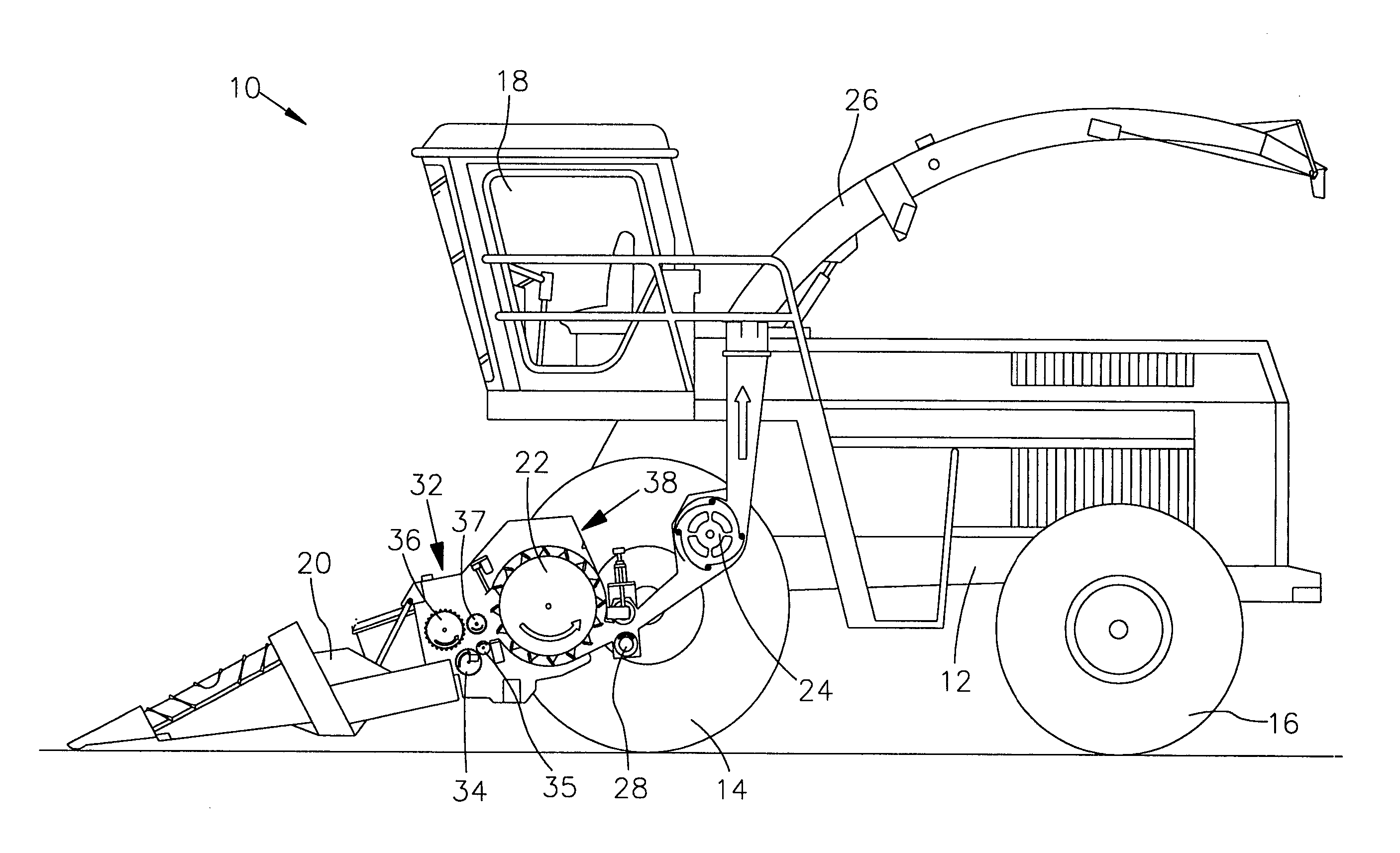
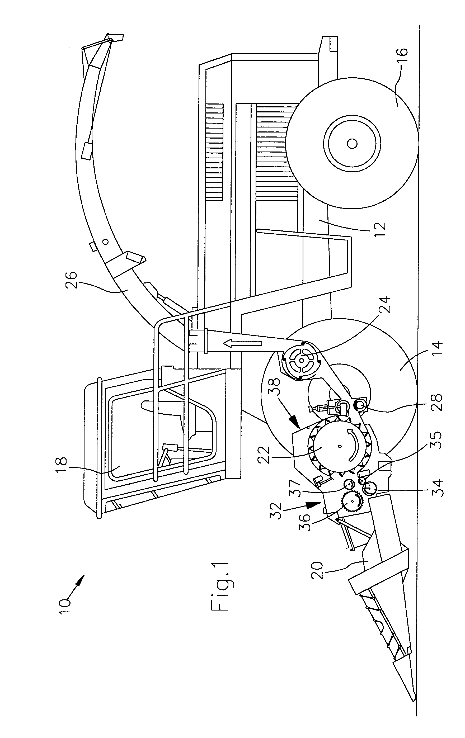
[0020]FIG. 1, a field chopper with a feeding device in a side view and in a schematic representation, and

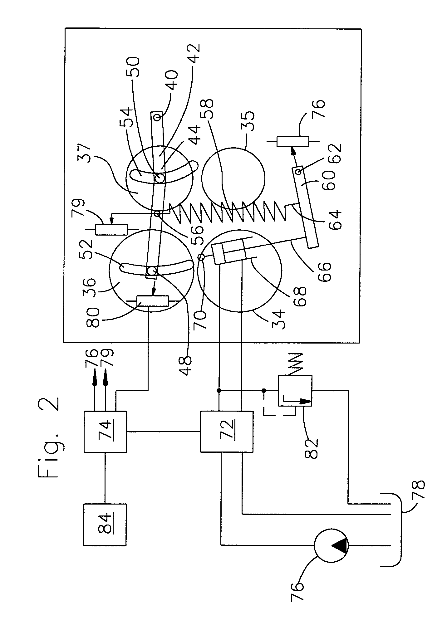
[0021]FIG. 2, a schematic side view of the feeding device and its control.

[0022] A self-propelled field chopper 10 shown in FIG. 1 is built on a frame 12, which is carried by wheels 14 and 16, which have front-wheel drive and rear-wheel steering. The operation of the field chopper 10 is performed from a driver cabin 18, from which a crop pick-up device 20 constructed in the present embodiment as a corn-harvesting header can be seen. Material, e.g., corn, grass, or the like, picked up from the ground by means of the crop pick-up device 20 is fed by a feeding device 32 arranged in a feed channel of the field chopper 10 with lower feedrolls 34, 35 and upper feedrolls 36, 37 to a chopping device 22 in the form of a chopping drum, which chops this material into small pieces...


PUM


Abstract

The invention relates to a feeding device (32) for a field chopper (10), comprising:
at least one rotatable lower feedroll (34, 35),
at least one rotatable upper feedroll (36, 37), between which a windrow can be fed and led to a chopping device (22),
and an external force-activated adjustment drive (68), with which the position of at least one of the feedrolls (36, 37) can be changed relative to the other feedroll (34, 35).
It is proposed that a spring (58) be arranged between the adjustment drive (68) and the feedroll (36, 37) that can be moved by this drive.
The spring (58) enables the movable feedroll (36, 37) to react more quickly or immediately to sudden changes in windrow height independent of the inertia of the adjustment drive (68).

Description

FIELD OF THE INVENTION [0001] The invention relates to a feeding device for a field chopper, comprising at least one rotatable lower feedroll, at least one rotatable upper feedroll, between which a windrow can be fed and led to a chopping device, and an external force-activated adjustment drive, with which the position of at least one of the feedrolls can be changed relative to the other feedroll. BACKGROUND OF THE INVENTION [0002] Field choppers are used in agriculture in order to cut or collect crop from a field by means of a crop pick-up device, to feed crop to a chopping device, usually a chopping drum or a slice chopper, via a feeding device, in order to chop the crop and to eject it onto a transport vehicle, usually after being accelerated by means of a blower, through an ejection elbow whose position is adjustable. In most cases, the harvested plants are used as silage for feeding animals or, in recent times, for biogas production. [0003] In currently used field choppers (see...

Claims


Application Information

Patent Timeline
IPC IPC(8): A01D61/00
CPCA01F29/10
Inventor SCHAFER, RAINERDOLD, MATTHEW GEORGE
Owner DEERE & CO
Why Eureka
Try Eureka