Direct current link inductor for power source filtration

a technology of direct current and inductor, which is applied in the direction of inductance, variable inductance, core/yokes, etc., can solve the problems of inconvenient control of the magnetic field generated by the permanent magnet, large inductance, and heavy weight, and achieve the effect of net h

Inactive Publication Date: 2007-05-24
HAMILTON SUNDSTRAND CORP
View PDF7 Cites 19 Cited by
  • Summary
  • Abstract
  • Description
  • Claims
  • Application Information

AI Technical Summary

Benefits of technology

[0008] The present invention inserts an electromagnetic H field into the inductor that opposes the H field generated by the DC that passes through its primary winding. The net H field is thus reduced and the magnetic operating point is then within a linear region of the inductor's hysteresis loop without the introduction of a large air gap. In one possible embodiment, the inductor has an auxiliary winding and a current passes through the auxiliary winding that creates an opposing H field. A feedback circuit may control the amount of current passing through the auxiliary winding to adjust the opposing H field to keep the magnetic operating point of the inductor in a linear region of the inductor's hysteresis loop regardless of DC current that passes through its primary winding.
[0009] Generally, the invention comprises an inductor with a primary winding on a magnetic core that produces a primary magnetic field H1 with a current I1, comprising: an electromagnetic field source that generates a secondary magnetic field H2 in the core that opposes the primary magnetic field H1 to produce a low net magnetic field HNET in the core to prevent magnetic saturation of the core.

Problems solved by technology

In short, high-level DC passing through an inductor requires that the inductor be larger, heavier and more costly than if there were no DC passing through it.
First, there is no convenient way to control the magnetic field generated by the permanent magnet.
Another disadvantage is that materials that have sufficient magnetic retentivity to be suitable for use as the permanent magnet have low permeability and therefore introduce an equivalent air gap when placed within the magnetic core of the inductor.

Method used


Image

  • Direct current link inductor for power source filtration
  • Direct current link inductor for power source filtration
  • Direct current link inductor for power source filtration

Examples


Embodiment Construction

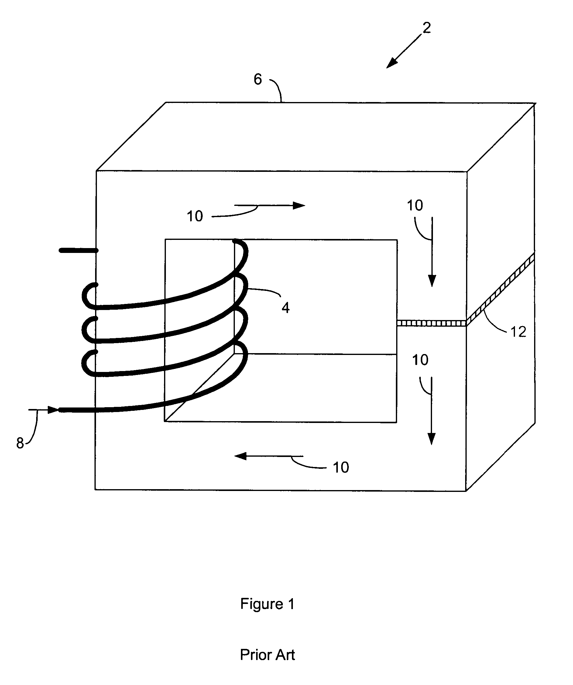
[0014]FIG. 1 is a perspective view of a typical inductor 2 according to the prior art. The inductor 2 has a primary winding 4 of N turns on a magnetic core 6. The primary winding 4 carries a current I along a direction indicated by arrow 8. The current I generates a magnetic field H along a magnetic path indicated by arrows 10. The magnetic core 6 has an air gap 12 that is placed across the magnetic path 10. For the typical inductor 2, the magnetic field H may be represented by: H=KNIIe

wherein K is a constant and Ie is the effective length of the magnetic path 10. Of course, the air gap 12 increases the effective length of the magnetic path 10, and thereby it reduces the possibility of magnetic saturation by reducing H.

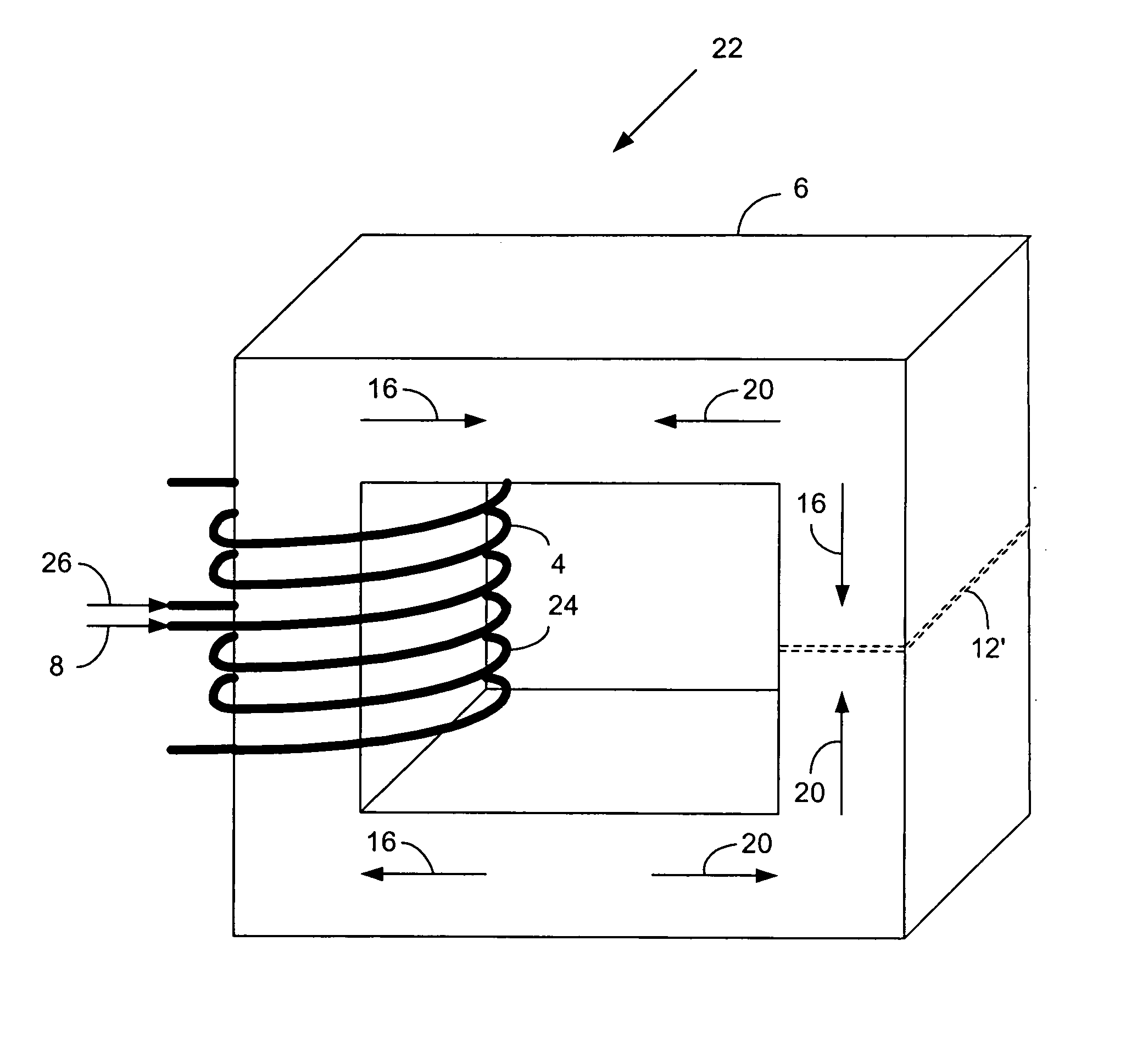
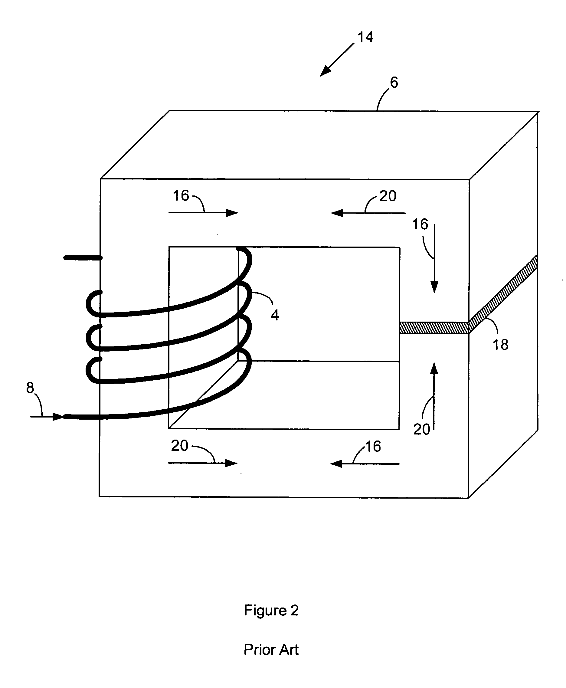
[0015]FIG. 2 is a perspective view of another inductor 14 according to the prior art. The inductor 14 has a primary winding 4 of N turns on a magnetic core 6. The primary winding 4 carries a current I1 along a direction indicated by arrow 8. The current I1 generate...


PUM

PropertyMeasurementUnit
magnetic field H1aaaaaaaaaa
magnetic field H2aaaaaaaaaa
magnetic fieldaaaaaaaaaa

Abstract

An inductor with a primary winding on a magnetic core that produces a primary magnetic field H1 with a current I1 has an electromagnetic field source that generates a secondary magnetic field H2 in the core that opposes the primary magnetic field H1 to produce a low net magnetic field HNET in the core to prevent magnetic saturation of the core.

Description

FIELD OF THE INVENTION [0001] The invention relates to electrical power sources for supplying and filtering direct current (DC) power, and more particularly to such power sources that have inductive filter elements. BACKGROUND OF THE INVENTION [0002] Electrical power sources that supply and filter DC to a load, such as sources that convert alternating current (AC) current to DC current for a load, generally comprise a rectifier circuit for converting the AC current to pulsating DC current and a filter circuit for converting the pulsating DC to steady-state DC. The rectifier circuit connects to the filter circuit by way of a DC link that generally comprises an inductor that serves as part of the filter circuit to form a choke-input filter circuit. Of course, the total current, including ripple current through the filter circuit and steady-state current through a load applied to the output of the filter circuit passes through the inductor. The total energy stored in the inductor is ½ ...

Claims


Application Information

Patent Timeline
Patent Type & Authority Applications(United States)
IPC IPC(8): H01F27/34
CPCH01F3/14H01F27/34H01F27/42H01F29/14H01F37/00H01F2003/103H03H7/09
Inventor CLEMMONS, JAMES H.
Owner HAMILTON SUNDSTRAND CORP
Why Eureka
Try Eureka