Liquid crystal display devices with high transmittance and wide viewing angle

a liquid crystal display and transmittance technology, applied in static indicating devices, instruments, non-linear optics, etc., can solve the problems of limited lcds, multi-domain tn typed lcds, and inadequate 60-degree viewing angles for large lcd tvs and monitors. achieve high transmittance, wide viewing angle, and high aperture ratio

Inactive Publication Date: 2007-05-24
UNIV OF CENT FLORIDA RES FOUND INC +1
View PDF9 Cites 58 Cited by
  • Summary
  • Abstract
  • Description
  • Claims
  • Application Information

AI Technical Summary

Benefits of technology

[0010] A primary objective of the invention is to provide new methods, systems, apparatus and devices for a liquid crystal display device in which the electrodes are designed to provide a high aperture ratio, high transmittance and a wide viewing angle.
[0012] A third objective of the invention is to provide new methods, systems, apparatus and devices for maintaining a high storage capacitance by including an additional pixel auxiliary electrode that occupies a small ratio of the transparent area to increase the aperture ratio and transmittance of the liquid crystal display.
[0014] In an embodiment, the liquid crystal display includes an insulating layer between the substrate and the alignment layer and the common electrodes are on the substrate and the pixel electrodes are on the insulating layer. In yet another embodiment, at least one phase retardation film is layered between one of the substrates and the corresponding one of the polarizing layers to improve the viewing angle.

Problems solved by technology

However, multi-domain in TN typed LCDs such as the two or four-domain TN LCDs are limited in improving the viewing angle to achieve a contrast ratio approximately >10:1 confined in a viewing cone at approximately 35 degrees.
However, a 60-degree viewing angle is inadequate for large LCD TVs and monitors, especially for solving the problem of non-uniform gray scale at larger viewing angle.
Each has advantages and disadvantages, however problems still exist.

Method used


Image

  • Liquid crystal display devices with high transmittance and wide viewing angle
  • Liquid crystal display devices with high transmittance and wide viewing angle
  • Liquid crystal display devices with high transmittance and wide viewing angle

Examples


Embodiment Construction

[0043] Before explaining the disclosed embodiments of the present invention in detail it is to be understood that the invention is not limited in its application to the details of the particular arrangements shown since the invention is capable of other embodiments. Also, the terminology used herein is for the purpose of description and not of limitation.

[0044] The following is a list of the reference numbers used in the drawings and the detailed specification to identify components:

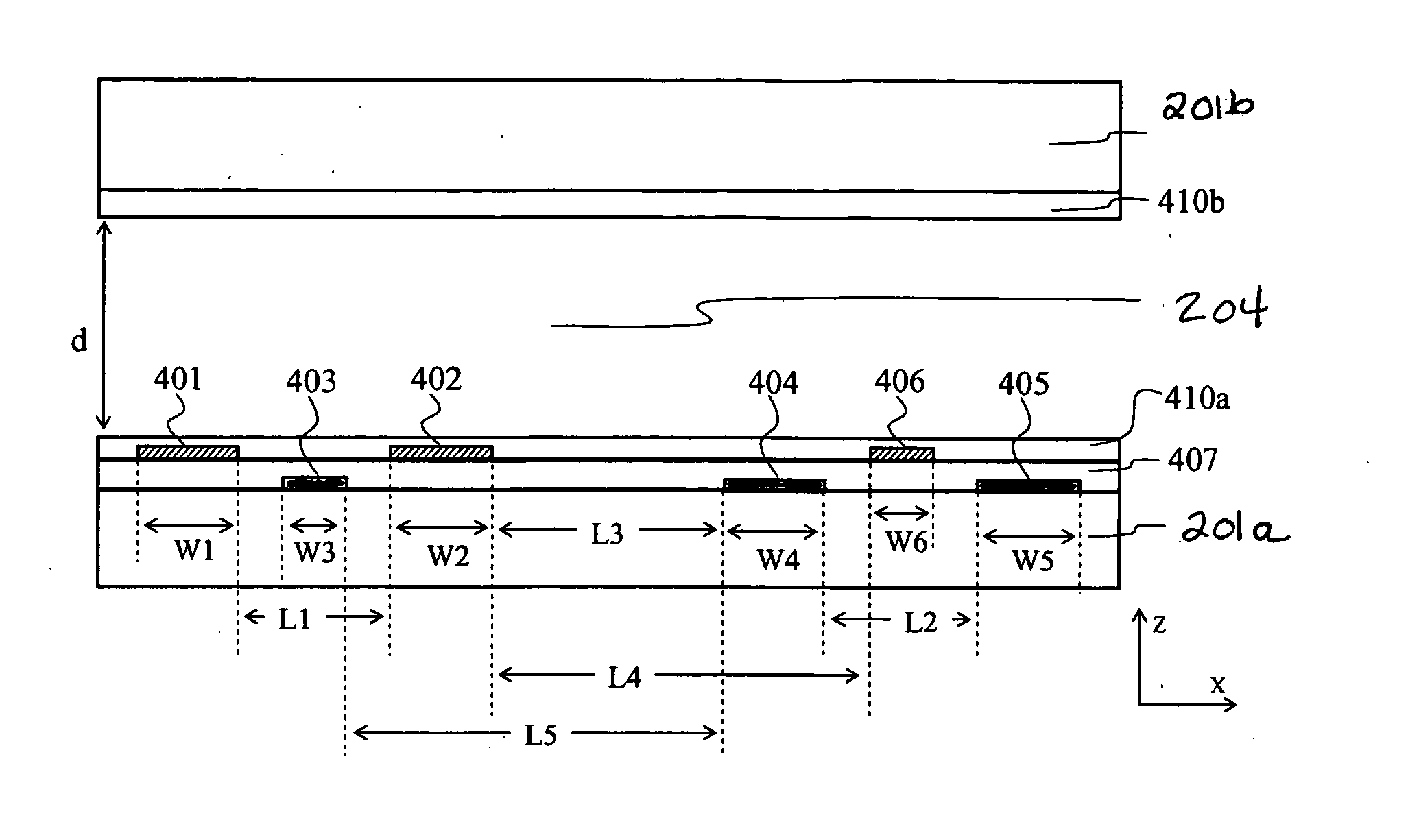
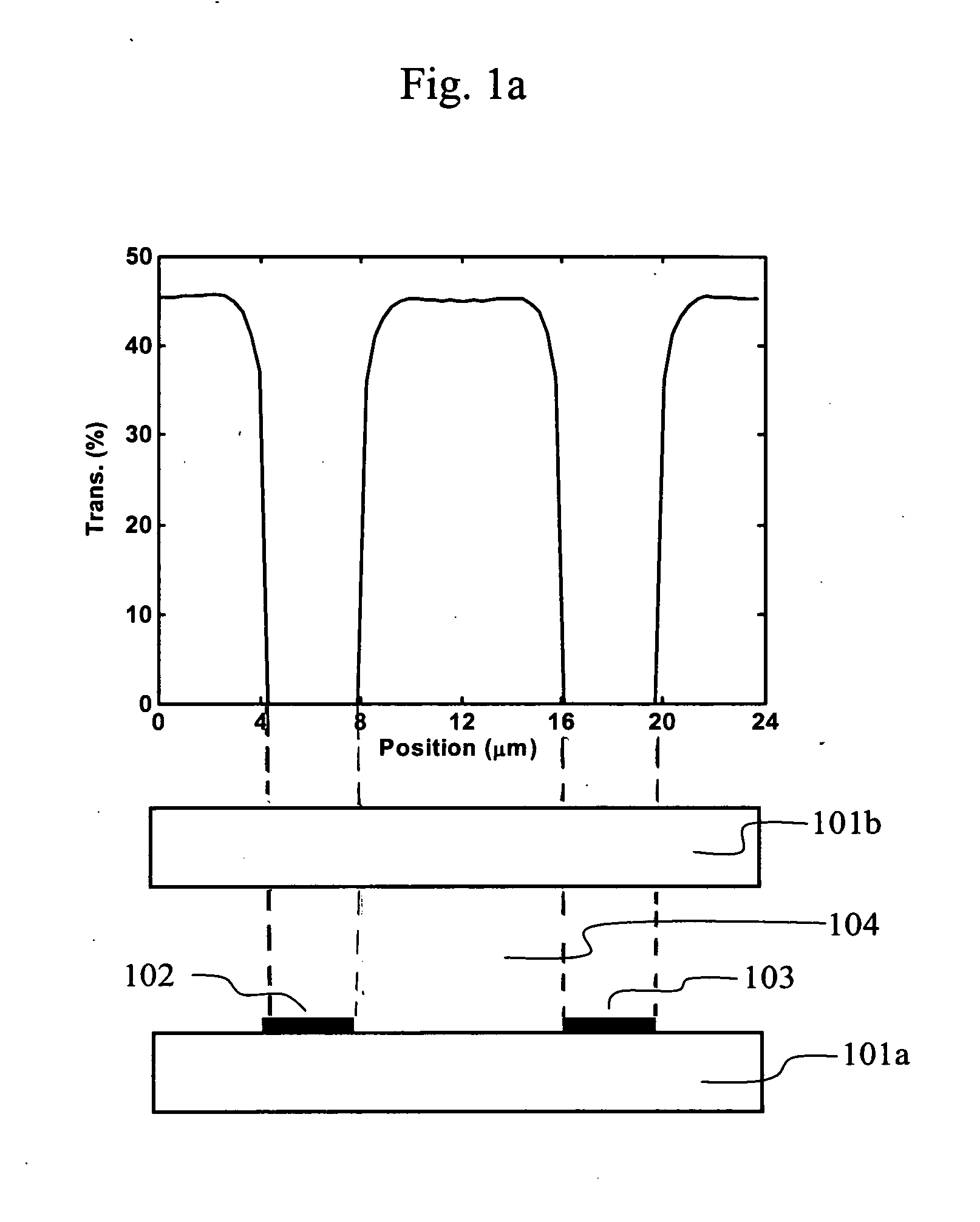
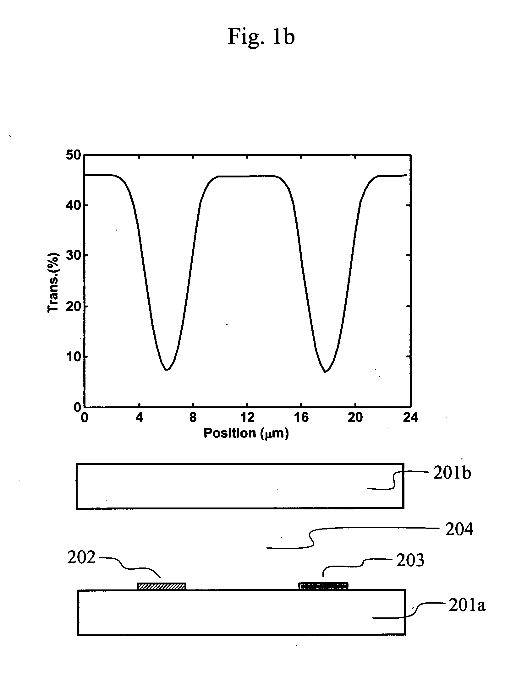
101afirst substrate101bsecond substrate102electrode103electrode104liquid crystal layer201afirst substrate201bsecond substrate202common electrode203pixel electrode204liquid crystal layer301common electrode302common electrode303pixel electrode304pixel electrode305pixel electrode306common electrode401common electrode402common electrode403pixel electrode404pixel electrode405pixel electrode406common electrode407insulating layer410aalignment layer410balignment layer501common electrode502common electrode503p...


PUM

PropertyMeasurementUnit
thicknessaaaaaaaaaa
thicknessaaaaaaaaaa
thicknessaaaaaaaaaa

Abstract

Apparatus, methods, systems and devices for high aperture ratio, high transmittance, and wide viewing angle liquid crystal display having first and second substrates each with an alignment layer and polarizer on the interior and exterior surface thereof and a liquid crystal material therebetween forming plural pixels each having a common electrode group and a pixel electrode group each having at least one common and pixel electrode. A fringe field drives the molecules in the regions above and below the electrodes and a horizontal field drives the molecules between the electrode groups to achieve high transmittance. In an embodiment an insulating layer separates the substrate and alignment layer and the pixel electrodes are on the substrate and the common electrodes are on the insulating layer. In another embodiment a compensation film is layered between one of the substrates and corresponding polarizer.

Description

FIELD OF THE INVENTION [0001] The present invention is related to liquid crystal displays, and more particularly to a apparatus, methods, systems and devices for a high aperture ratio, high transmittance, and wide viewing angle liquid crystal display device driven by groups of electrodes in each pixel area that is useful for high-definition televisions and monitors which require high brightness and large viewing angle performance. BACKGROUND AND PRIOR ART [0002] Generally, based on the on-state orientation scheme of liquid crystal major axis, the direction of the axis is referred to as directors, there are two primary types of liquid crystal displays LCDs. The first type of LCD has directors that rotate mainly in a plane orthogonal to a substrate and the second type has directors rotating mainly in a plane parallel to the substrate. [0003] The most typical mode of the first category is the twisted nematic liquid crystal display TN LCDs, in which the electrodes are configured on both...

Claims


Application Information

Patent Timeline
Patent Type & Authority Applications(United States)
IPC IPC(8): G02F1/1343
CPCG02F1/133634G02F1/134363G02F2001/134372G02F1/134372
Inventor GE, ZHIBINGZHU, XINYUWU, SHIN-TSONWU, THOMAS XINZHANG
Owner UNIV OF CENT FLORIDA RES FOUND INC
Why Eureka
Try Eureka