Holographic memory device

a memory device and holographic technology, applied in the field of holographic memory devices, can solve problems such as the inability to obtain a proper reproduction signal, and achieve the effect of high-quality reproduction data

Inactive Publication Date: 2007-05-24
SANYO ELECTRIC CO LTD +1
View PDF1 Cites 10 Cited by
  • Summary
  • Abstract
  • Description
  • Claims
  • Application Information

AI Technical Summary

Benefits of technology

[0021] According to the present invention, even when a tilt error occurs in a direction vertical to a surface including the optical axes of the data light and reference light, it is possible to obtain high-quality reproduction data by adjusting the rotational position of a holographic memory medium to a proper position.

Problems solved by technology

In this case, even when the reference light actuator is controlled, an angle between the interference fringe and the reference light is different from that during recording, making it impossible to obtain a proper reproduction signal.

Method used


Image

  • Holographic memory device
  • Holographic memory device
  • Holographic memory device

Examples


embodiment 1

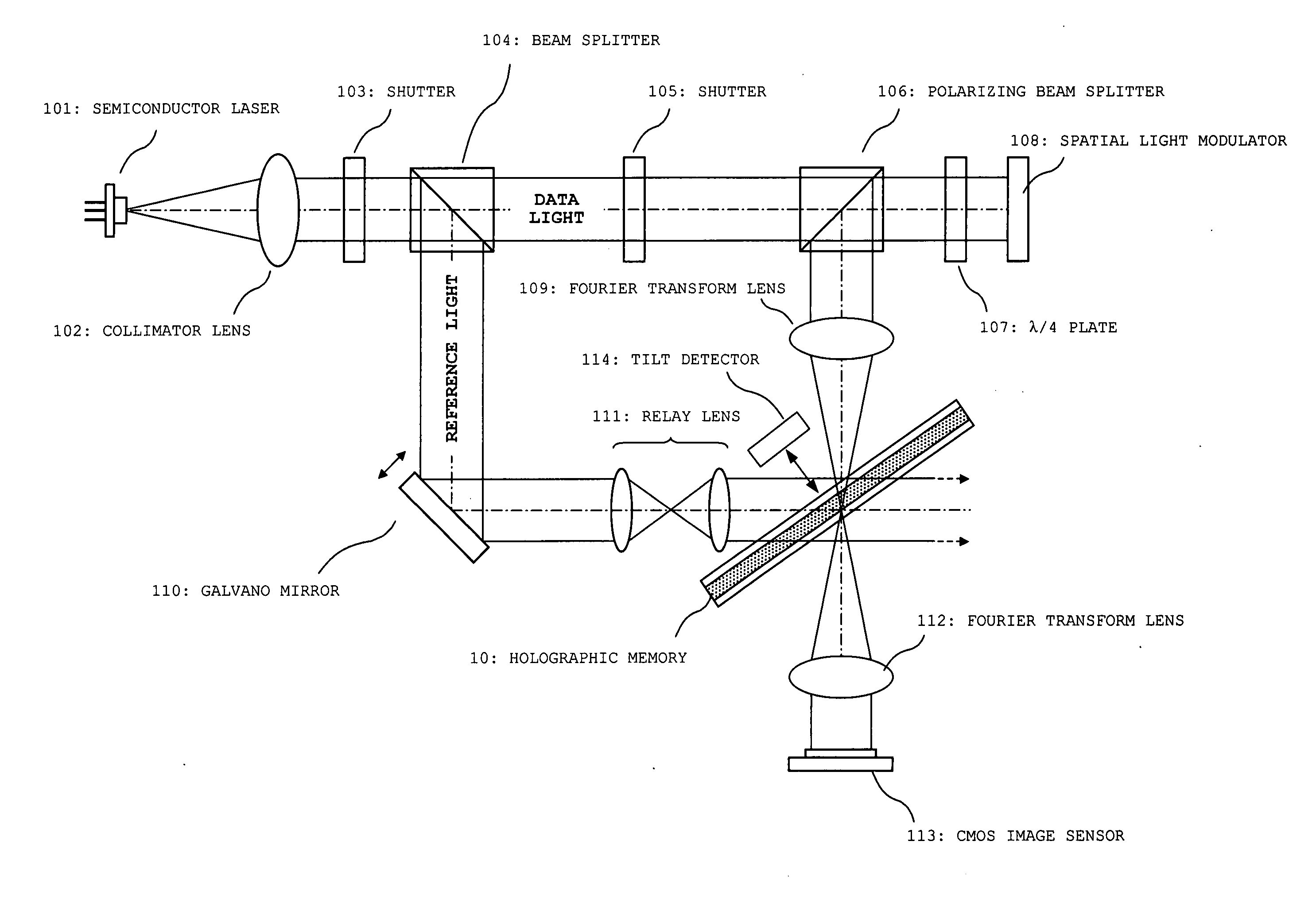
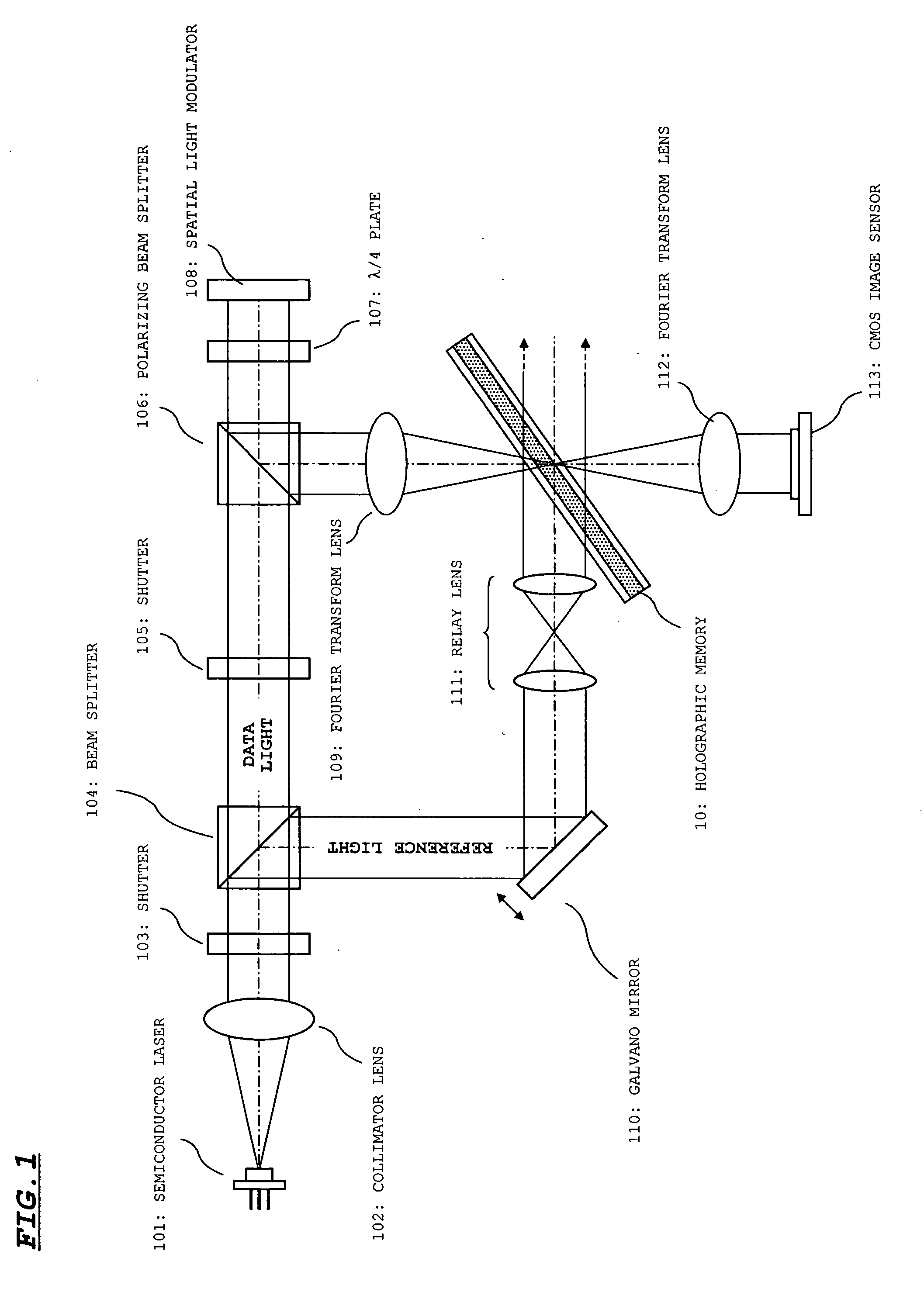
[0035]FIG. 1 shows an optical system of a holographic memory device according to Embodiment 1 of the present invention. The optical system shown in FIG. 1 is used when information is recorded / reproduced in a transmission type of holographic memory 10.

[0036] As shown in FIG. 1, this optical system includes a semiconductor laser 101, a collimator lens 102, a shutter 103, a beam splitter 104, a shutter 105, a polarizing beam splitter 106, a λ / 4 plate 107, a spatial light modulator 108, a Fourier transform lens 109, a galvano mirror 110, a relay lens 111, and a Fourier transform lens 112, and a CMOS (Complementary MOS) image sensor 113.

[0037] The semiconductor laser 101 emits a laser light of a wavelength suited to the holographic memory 10. The collimator lens 102 converts the laser light made incident from the semiconductor laser 101 into a parallel light. The shutter 103 includes a mechanical shutter or the like, and passes / blocks a laser light according to a control signal. Specif...

embodiment 2

[0085] According to Embodiment 1 of the present invention, the SNR of the reproduction signal is actually calculated, and the disk circumferential direction position of the holographic memory 10 is set in the position of the best SNR of the reproduction signal. According to this embodiment, however, a tilt amount of a holographic memory 10 is detected by a tilt detector, and a disk circumferential direction position of the holographic memory 10 is set in a position where a tilt error may be suppressed, based on the detected tilt amount. According to this embodiment, as in the case of Embodiment 1 of the present invention, it is presumed that data light and reference light are made incident on the holographic memory 10 in a tangential direction.

[0086] According to this embodiment, a table in which a tilt amount of a radial direction of the holographic memory 10 is associated with a correction amount of the disk circumferential direction there of is held in a memory incorporated in a...


PUM


Abstract

To properly reproduce information from a holographic memory even when a tilt error occurs in a direction vertical to a surface including optical axes of data light and reference light. During reproduction, a holographic memory (10) is fed stepwise from an initial access position with respect to a reproduction target block within a fixed back and forth range in a disk circumferential direction. In each stepwise-fed position, an SNR of a reproduction signal is calculated by an SNR calculation circuit (19) to detect the quality of the reproduction signal. A disk circumferential direction position in which an SNR becomes best is set in a circumferential direction position with respect to the reproduction target block.

Description

BACKGROUND OF THE INVENTION [0001] 1. Field of the Invention [0002] The present invention relates to a holographic memory device for reproducing information from a holographic memory in which information is recorded by fixing an interference fringe generated by an interference caused therein between a data light and a reference light, and is particularly suitable for use in correcting a tilt error between the holographic memory and the reference light. [0003] 2. Description of the Related Art [0004] Generally, in the holographic memory, information is recorded by fixing an interference fringe, which is generated by an interference caused therein between a data light and a reference light, on a holographic memory material layer. In this case, the data light is subjected to spatial light modulation according to the information to be recorded. Therefore, when the data light and the reference light are applied to the holographic memory, a bright and dark interference fringe is generated...

Claims


Application Information

Patent Timeline
Patent Type & Authority Applications(United States)
IPC IPC(8): G03H1/28
CPCG11B7/0065G11B7/083G11C13/042
Inventor MATSUMURA, YOSHIYUKIREDMOND, IAN RUSSELL
Owner SANYO ELECTRIC CO LTD
Why Eureka
Try Eureka