
Disk recording medium, disk production method, disk drive apparatus

a technology of disk drive and recording medium, which is applied in the direction of recording signal processing, digital signal error detection/correction, instruments, etc., can solve the problems of disadvantageous prerecording method, difficult to form grooves and emboss pits with different depths from each other, and achieve high degree of reliability

Inactive Publication Date: 2007-05-24
SONY GRP CORP
View PDF14 Cites 23 Cited by
  • Summary
  • Abstract
  • Description
  • Claims
  • Application Information

AI Technical Summary

Benefits of technology

[0021] Taking the situations described above into consideration, it is an object of the present invention to record additional information to be recorded in advance together with address information appropriately and with a high degree of reliability.

Problems solved by technology

The pigment film change recording method is also called write-once recording method and allows data recording only once but does not allow re-writing, and therefore, it is suitably used for data storage applications and so forth.
The reason why a high degree of reliability is required is that, for example, if attributes or additional information for control is not obtained accurately, then an apparatus on the user side cannot execute such a control operation for establishing optimum recording conditions correctly.
However, if it is intended to achieve high density recording and reproduction onto and from an optical disk, the prerecording method by emboss pits is disadvantageous.
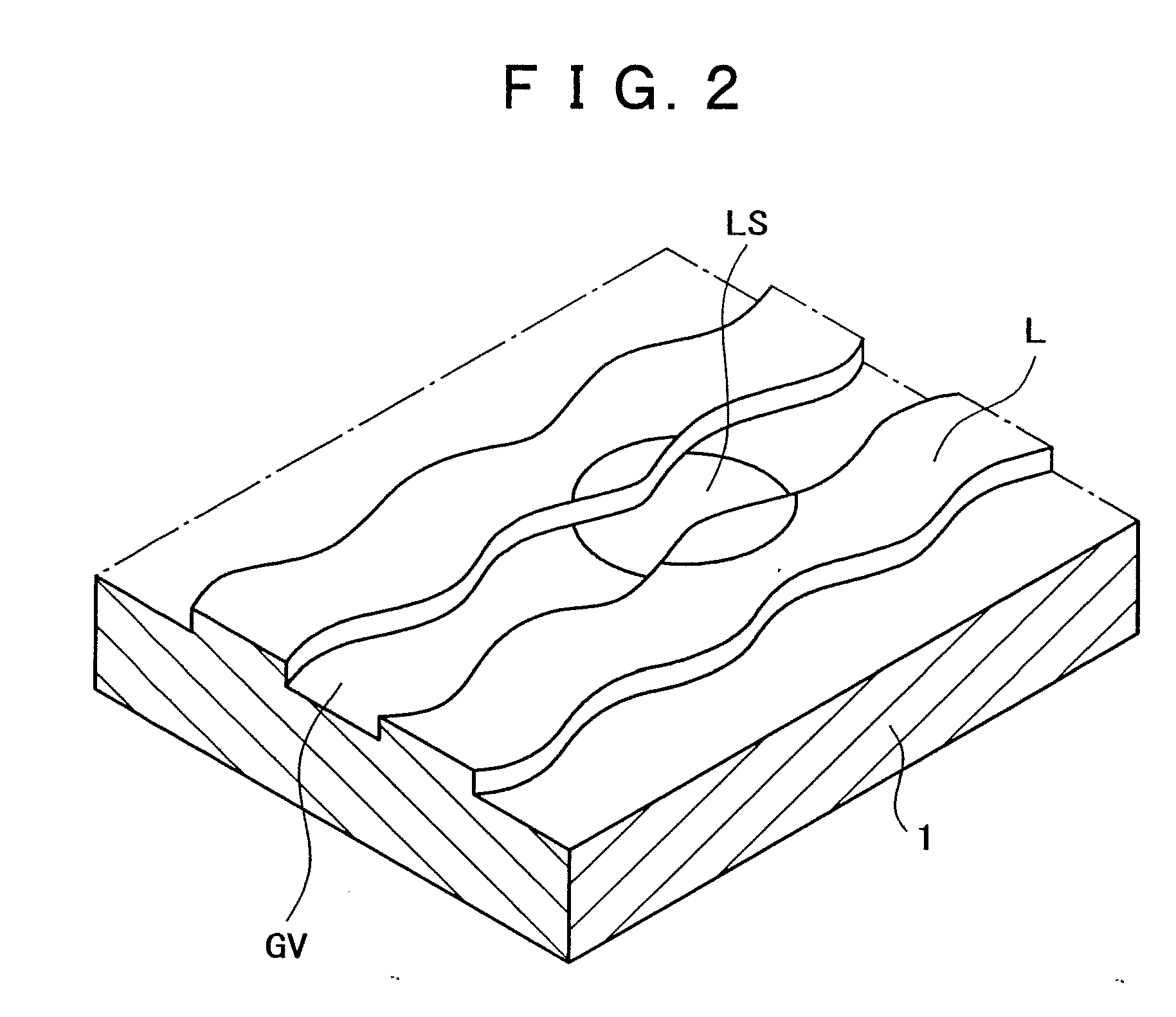
With a disk produced with a stamper such that a groove and emboss pits are formed at a time, it is very difficult to form the groove and the emboss pits with different depths from each other.
Therefore, it cannot be avoided to make the depth of the emboss pits equal to the depth of the groove.
However, where the depth of the emboss pits is small, there is a problem that a signal of a good quality cannot be obtained from the emboss pits.
After all, a good solution to a common depth to the groove and the emboss pits cannot be obtained.

Method used


Image

  • Disk recording medium, disk production method, disk drive apparatus
  • Disk recording medium, disk production method, disk drive apparatus
  • Disk recording medium, disk production method, disk drive apparatus

Examples


Embodiment Construction

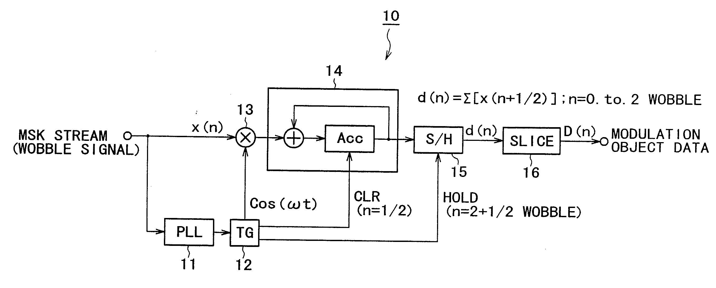
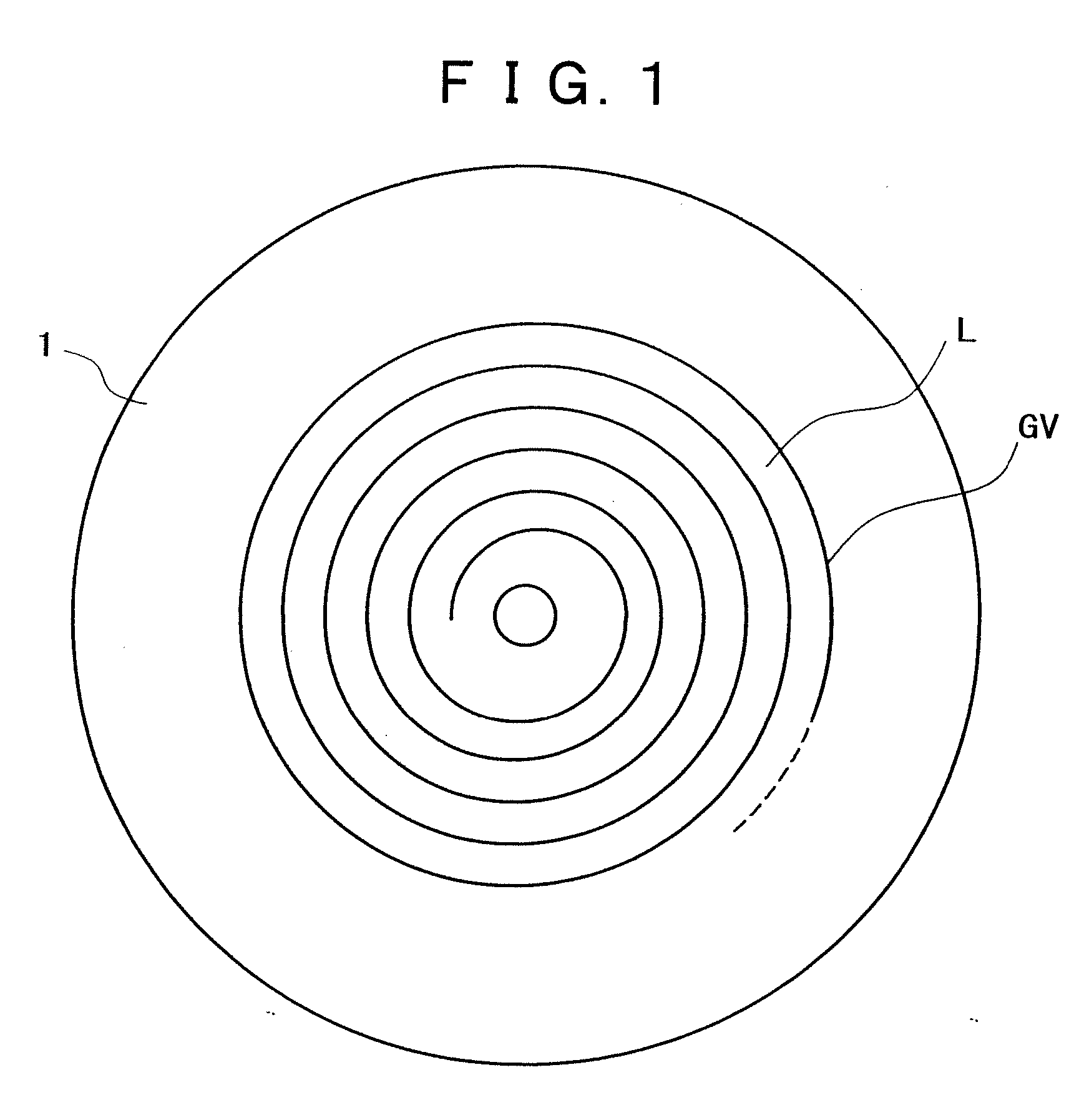
[0074] In the following, an optical disk as an embodiment of the present invention is described, and a disk drive apparatus (recording and reproduction apparatus) which performs recording and reproduction onto and from the optical disk and a mastering apparatus used for production of the optical disk are described. The description is given in the following order.

1. Wobbling System of the Disk

[0075] 1-1. General Description of the Wobbling System [0076] 1-2. MSK Modulation [0077] 1-3. HMW Modulation [0078] 1-4. Summary

2. Application to a DVR [0079] 2-1. Physical Characteristics of a DVR Disk [0080] 2-2. ECC Format of the Data [0081] 2-3. Address Format

[0082] 2-3-1. Relationship Between Recording and Reproduction data and Addresses

[0083] 2-3-2. Sync Part

[0084] 2-3-3. Data Part

[0085] 2-3-4. Contents of the Address Information

[0086] 2-4. Address Demodulation Circuit

3. ECC Format of the Disk Information

4. Disk Drive Apparatus

5. Disk Production Method

1. Wobbling System o...


PUM

PropertyMeasurementUnit
diameteraaaaaaaaaa
radiusaaaaaaaaaa
track pitchaaaaaaaaaa

Abstract

A disk recording medium which can implement a recording method having a high degree of reliability for additional information is disclosed. The disk recording medium has a recording and reproduction region into and from which first data can be recorded and reproduced in accordance with a rewritable or write-once-read-many recording method and from which second data recorded in the form of wobbling of a groove can be reproduced. The second data includes address information and additional information. The additional information of the second data is coded in accordance with a first error correction method, and the coded additional information and the address information are recorded in a state coded in accordance with a second error correction method.

Description

TECHNICAL FIELD [0001] The present invention relates to a disk recording medium such as an optical disk and a disk production method for producing the disk recording medium as well as a disk drive apparatus for the disk recording medium. BACKGROUND ART [0002] As a technique for recording and reproducing digital data, a data recording technique is available which uses an optical disk (including a magneto-optical disk) such as, for example, a CD (Compact Disc), an MD (Mini-Disc) and a DVD (Digital Versatile Disc) as a recording medium. The optical disk is a general term for recording media of the type wherein laser light is illuminated upon a disk formed from a thin metal plate protected with plastic and a signal is read from a change in reflected light from the disk. [0003] Optical disks are divided into those of the type which can be used only for reproduction as known as, for example, a CD, a CD-ROM and a DVD-ROM and those of the type on which user data is recordable as known as an...

Claims


Application Information

Patent Timeline
Patent Type & Authority Applications(United States)
IPC IPC(8): G11B7/00G11B7/004G11B7/007G11B11/00G11B20/12G11B20/14G11B20/18
CPCG11B20/1217G11B20/18G11B20/1833G11B2020/10888G11B2020/1239G11B2020/1267H03M13/2906G11B2020/1287G11B2020/1836G11B2220/215G11B2220/216G11B2220/2537G11B2020/1272G11B7/007G11B20/12G11B7/004
Inventor KOBAYASHI, SHOEI
Owner SONY GRP CORP
Learn More