
Tomograph

a tomograph and ring technology, applied in the field of tomographs, can solve the problems of not being able to completely remove the ring artifact, the calibration method cannot correct the non-linear input-output characteristic, and the dark-band artifact attributable to beam hardening cannot be completely removed, so as to achieve the effect of reducing the ring artifa

Inactive Publication Date: 2007-05-24
HITACHI MEDICAL CORP
View PDF5 Cites 22 Cited by
  • Summary
  • Abstract
  • Description
  • Claims
  • Application Information

AI Technical Summary

Benefits of technology

[0006] The air calibration method can correct a distribution of intensities of radiation incident on a radiation detector or a variance of sensitivities of the radiation detector, and can greatly minimize the ring artifact. However, the air calibration method cannot correct the non-linear input-output characteristic of the radiation detector and therefore cannot completely remove the ring artifact. Moreover, the dark-band artifact attributable to beam hardening cannot be removed.

Problems solved by technology

However, the air calibration method cannot correct the non-linear input-output characteristic of the radiation detector and therefore cannot completely remove the ring artifact.
Moreover, the dark-band artifact attributable to beam hardening cannot be removed.
However, since the radiation absorption dose of the water phantom cannot be exactly agreed with that of a subject, the precision in removal is low.
In reality, it is nearly impossible to increase the number of samples.
The reason why it is nearly impossible to increase the number of samples is that it is time-consuming and labor-intensive to acquire measured data items.
It is time-consuming and labor-intensive.

Method used


Image

  • Tomograph
  • Tomograph
  • Tomograph

Examples


first embodiment

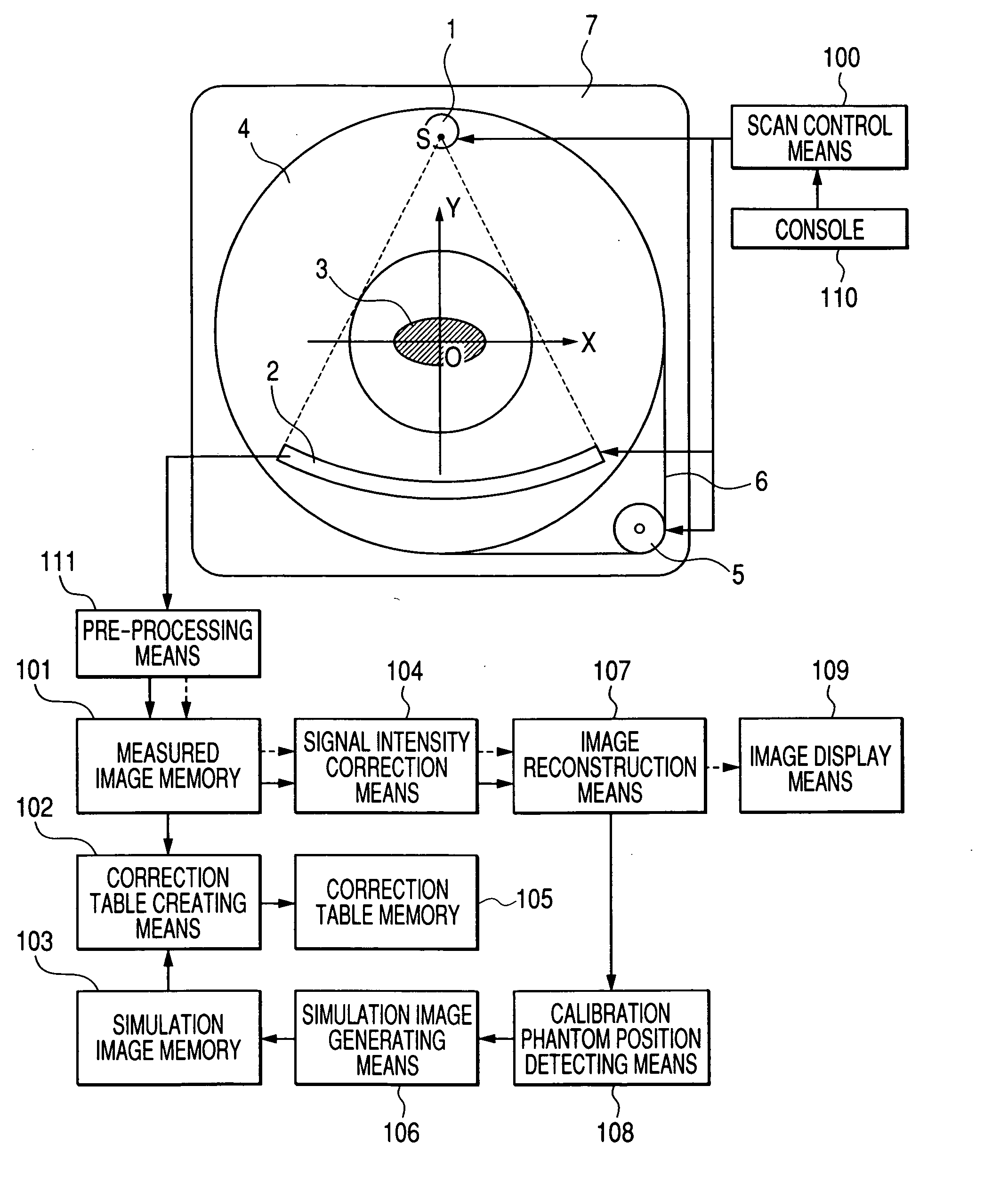
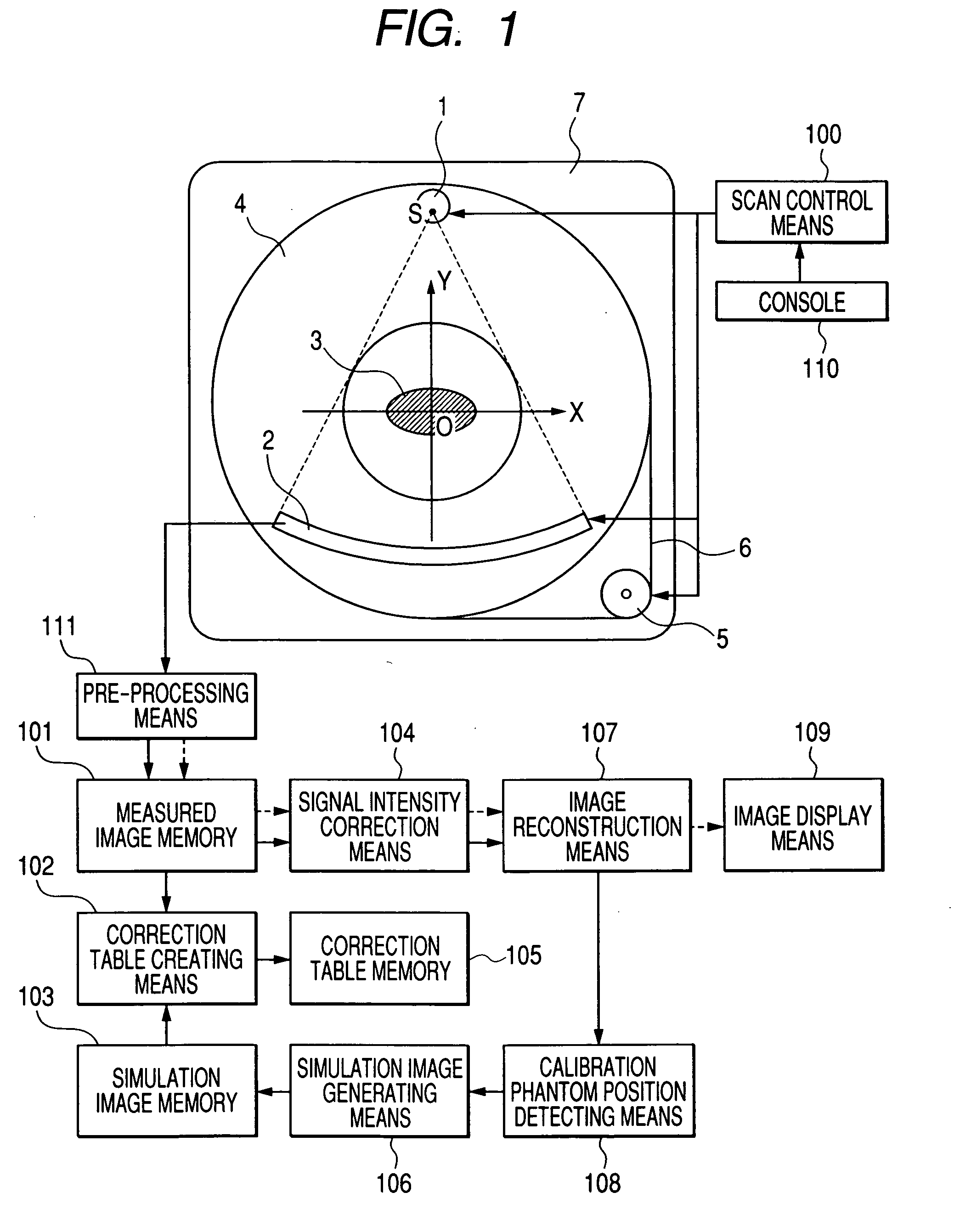
[0047]FIG. 1 is a front view illustrating a tomograph in accordance with the first embodiment of the present invention. The tomograph in accordance with the first embodiment includes an X-ray tube 1, an X-ray detector 2, a rotary panel 4, a driving motor 5, a driving belt 6, a gantry 7, a scan control means 100, a preprocessing means 111, a measured image memory 101, a correction table creating means 102, a simulation image memory 103, a signal intensity correction means 104, an image reconstruction means 107, a calibration phantom position detecting means 108, an image display means 109, and a console 110.

[0048] Hereinafter, the assembly of the X-ray tube 1 and X-ray detector 2 shall be called a scanning system. The scanning system is fixed to the rotary panel 4. The driving motor 5 rotates the rotary panel 4 and entire scanning system via the driving belt 6. The scanning system irradiates X-rays to a subject 3 from all around the subject, and produces X-ray transmitted images of ...

second embodiment

[0083] A tomograph in accordance with the second embodiment of the present invention will be described below. The tomograph in accordance with the second embodiment of the present invention uses a cylindrical phantom 1000 on behalf of the elliptic phantom 700 employed as a calibration phantom in the first embodiment. The other components of the tomograph are identical to those of the first embodiment described in conjunction with FIG. 1 to FIG. 6. An iterative description will be omitted.

[0084] FIGS. 10 are explanatory diagrams concerning a calculation method implemented in the simulation image generating means 106 included in the tomograph in accordance with the second embodiment of the present invention. Referring to FIGS. 10, a simulation image generation method will be described on the assumption that the cylindrical phantom 1000 is adopted as a calibration phantom. As already described, the orthogonal coordinate system XYZ is a stationary coordinate system defined in the gantr...


PUM


Abstract

The present invention provides a technology for reducing artifacts attributable to the non-linearity in the input-output characteristic of a radiation detector and beam hardening of radiation in a tomograph. The tomograph includes a scanning system that includes a generation means which generates radiation to be irradiated to a subject and a detection means which is opposed to the generation means in order to detect the radiation transmitted by the subject, and a rotation means that rotates the scanning system about the subject, and reconstructs a tomographic image of the subject using a plurality of transmitted images produced by projecting the radiation from a plurality of rotational angular positions while rotating the scanning system about the subject. The tomograph further includes: a first storage means in which measured images that are three or more transmitted images produced by rotating the scanning system about a plurality of phantoms including at least one phantom whose section perpendicular to an axis of rotation of the scanning system has different dimensions in two directions orthogonal to the axis of rotation are stored; a production means that produces calculated images as the transmitted images through calculation; a second storage means in which the produced calculated images are stored; and a correction means that corrects the intensities represented by the transmitted images of the subject according to the measured images and calculated images.

Description

TECHNICAL FIELD [0001] The present invention relates to a tomograph, or more particularly, to a technology for reducing artifacts in a tomographic image attributable to a change in radiation quality occurring in a subject or the non-linearity in the input-output characteristic of a radiation detector. BACKGROUND ART [0002] In tomographs, a reconstructed tomographic image of a subject (hereinafter a reconstructed image) may contain artifacts. The artifacts include a ring artifact that is an annular pattern contained in a reconstructed image, and a dark-band artifact that is a black band-like pattern appearing between images of high-radiation absorbent substances. The major factors of the ring artifact are that the sensitivity of a radiation detector varies from pixel to pixel or the input-output characteristic thereof is not ideal but is non-linear. Moreover, the major factor of the dark-band artifact is that radiation quality changes in a subject (beam hardening). Various methods ha...

Claims


Application Information

Patent Timeline
IPC IPC(8): G01D18/00A61B6/00
CPCA61B6/5258A61B6/583
Inventor UEKI, HIRONORIKONNO, YASUTAKA
Owner HITACHI MEDICAL CORP
Learn More